


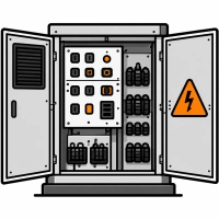
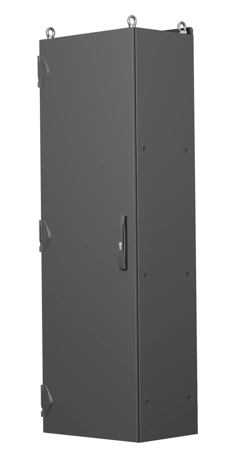
The main equipment cabinet is where the 3 kV DC circuit ends and control begins. The HV compartment contains a high-speed circuit breaker, an overcurrent/differential-current relay, an HV distribution board with fuses and contactors supplying traction inverters and converters, pre-charge resistors and energy meters. LV cabinets contain 110 V DC and 24 V DC control circuits: contactors, time-delay relays, automatic circuit breakers, controllers, terminal strips and measurement shunts; in newer vehicles they also house controllers, CAN and Ethernet buses, and brake solenoid valves controlled by binary signals.
Conditions here differ from those in an industrial cabinet. Short-circuit current in a 3 kV DC system can reach 50 kA, while a typical circuit on Polish lines has a time constant of 20 ms and a steady-state current of up to 20 kA. Vehicle protection must clear a short circuit before the substation circuit breaker operates - this is determined by the device’s operating time and current-limiting capability; breaking capacity alone is not sufficient. LV circuits operate over a wide temperature range and under continuous vibration, so the tripping characteristics of protective devices must not depend on ambient temperature, and contacts must remain reliable under vibration.
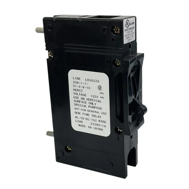
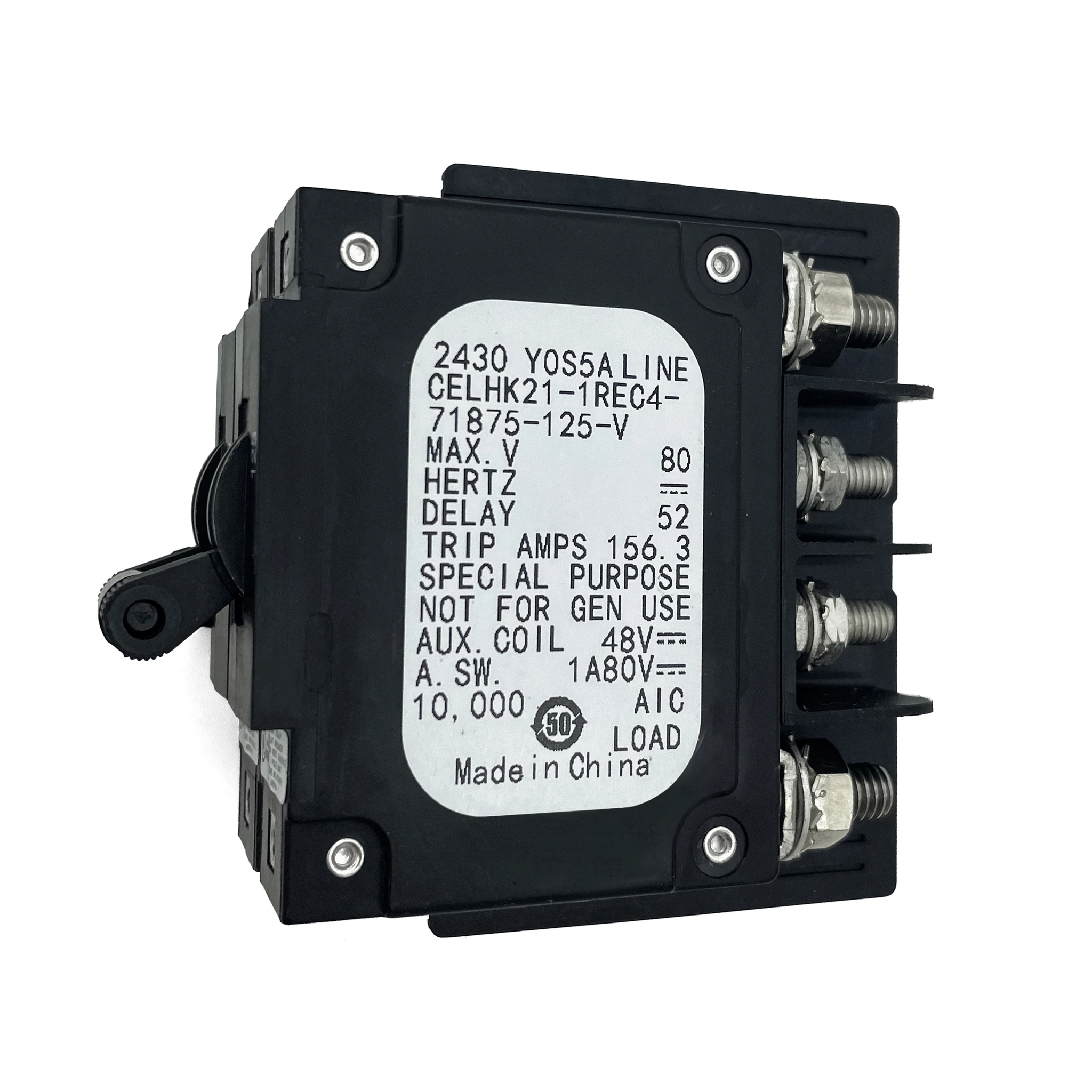
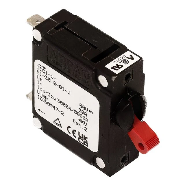
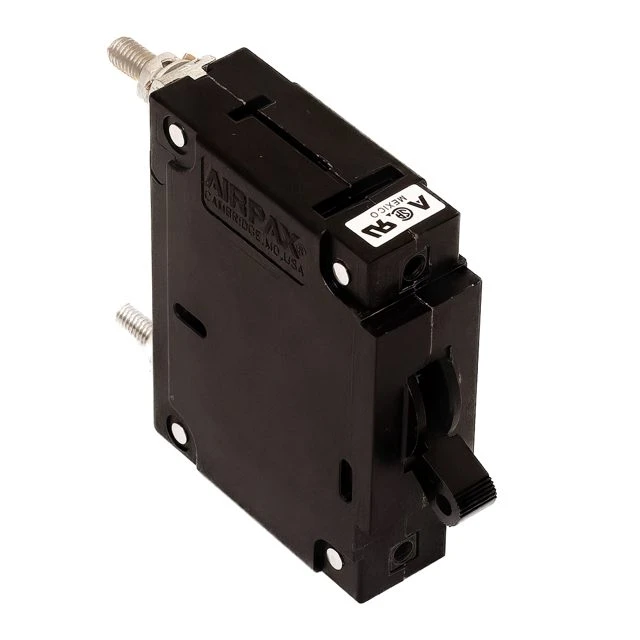
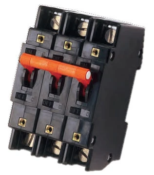
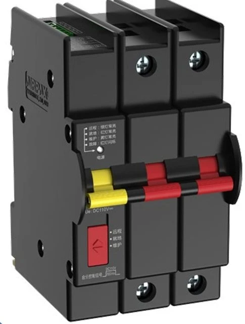
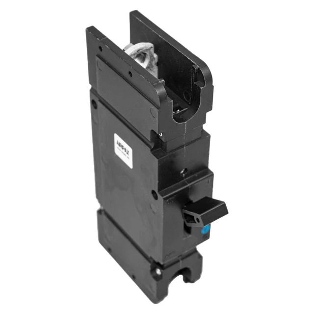
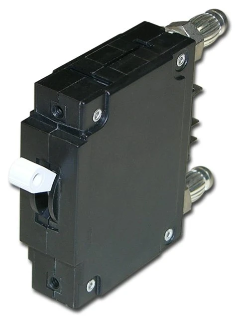
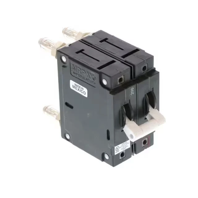
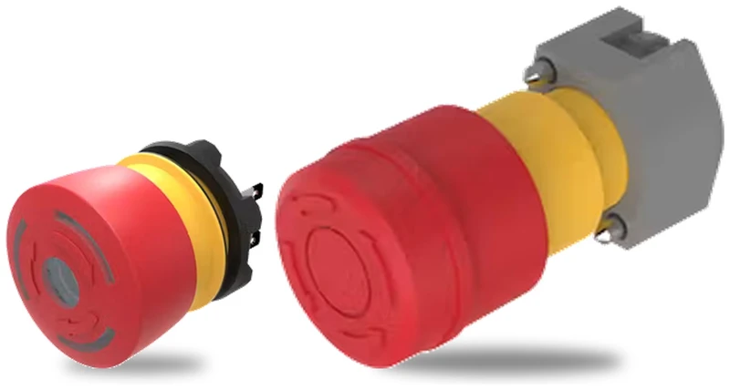
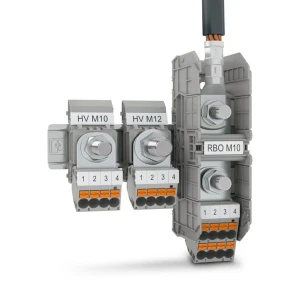
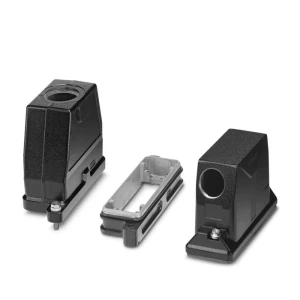
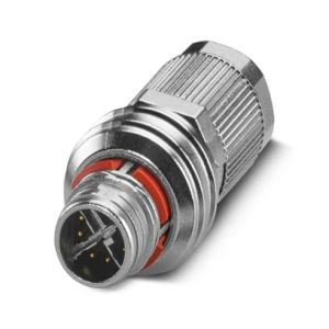
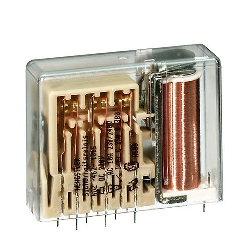
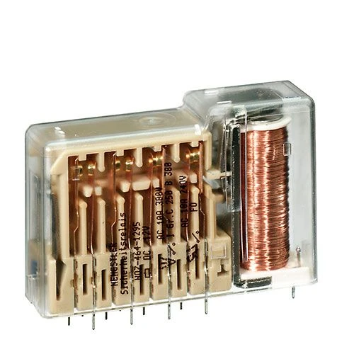
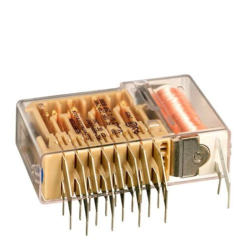
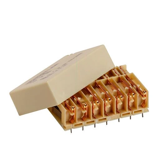
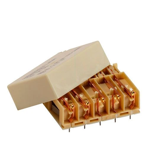
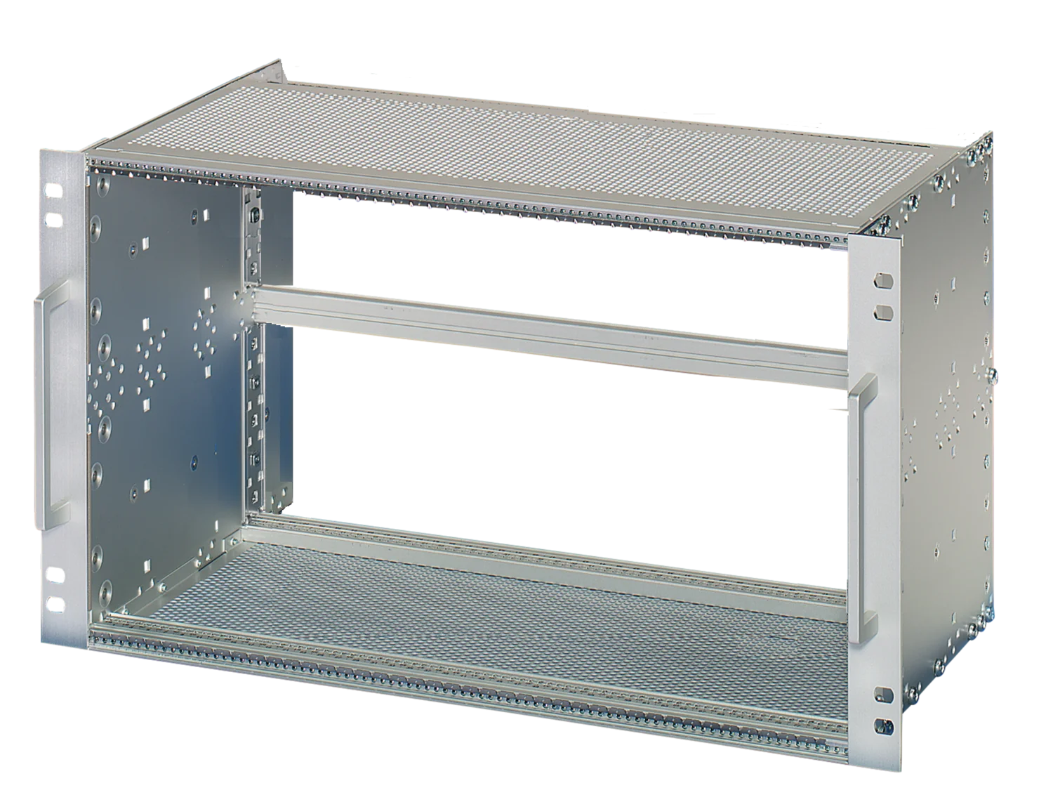
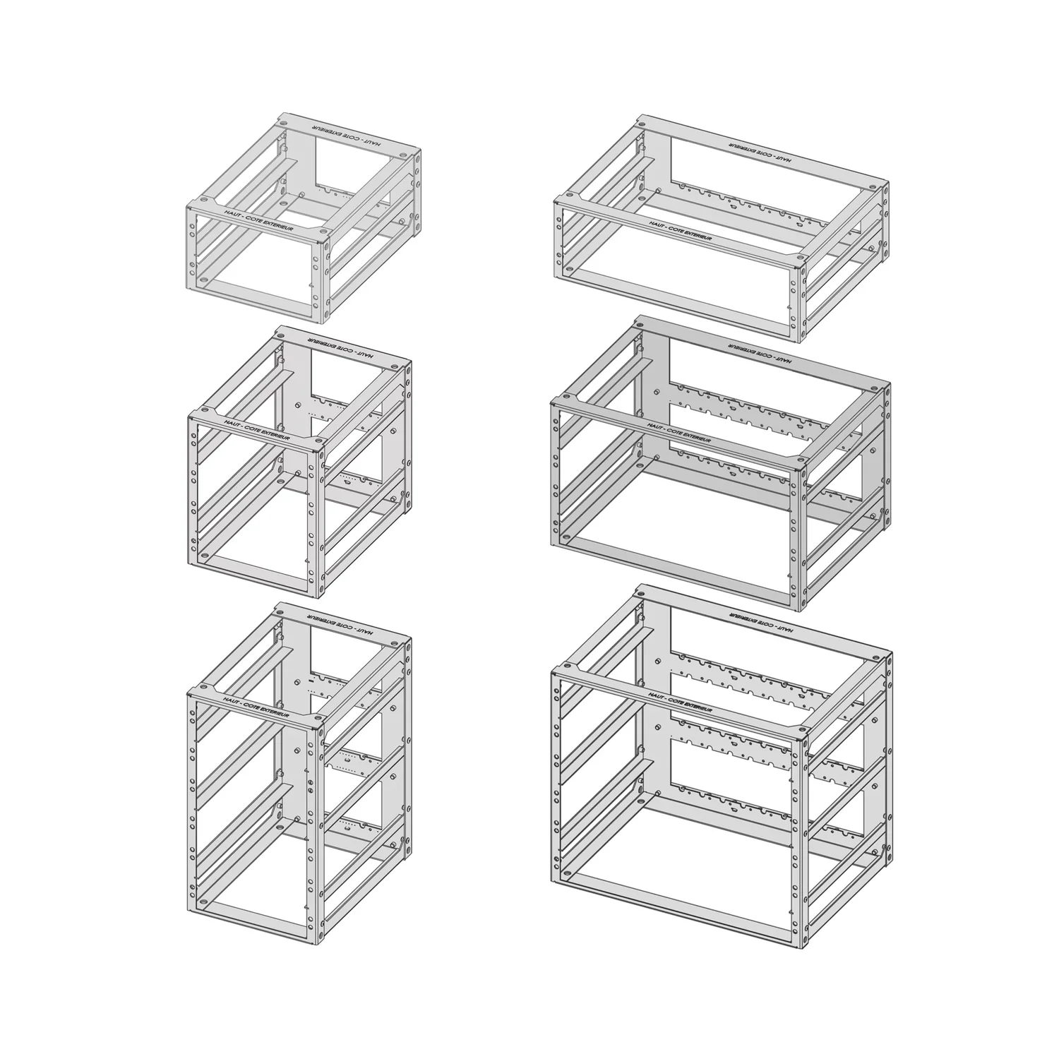
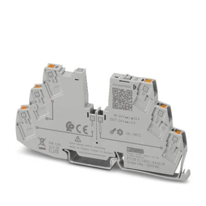
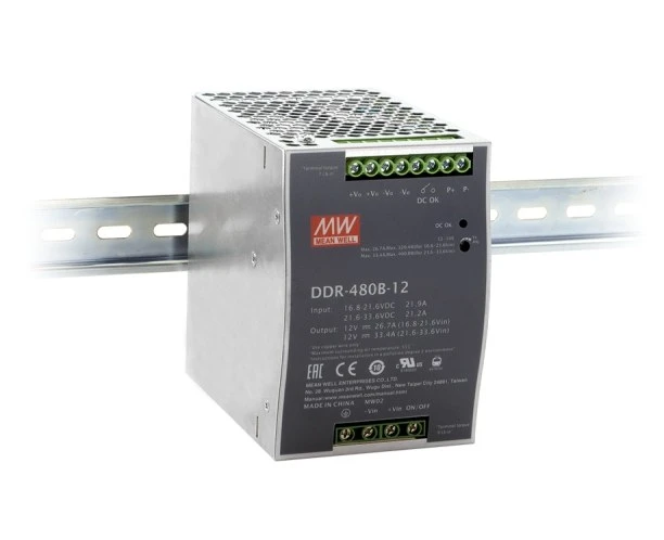
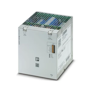
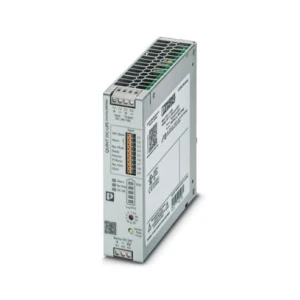
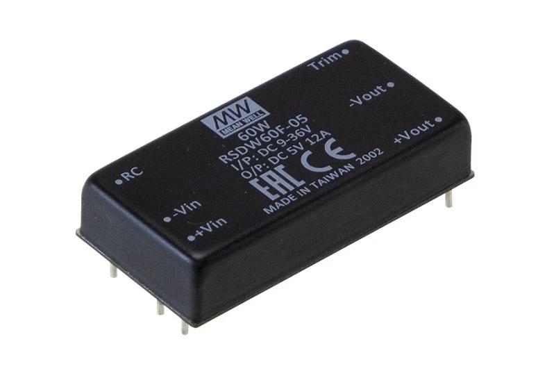
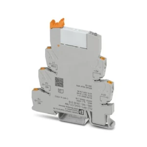
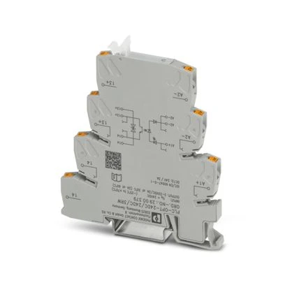
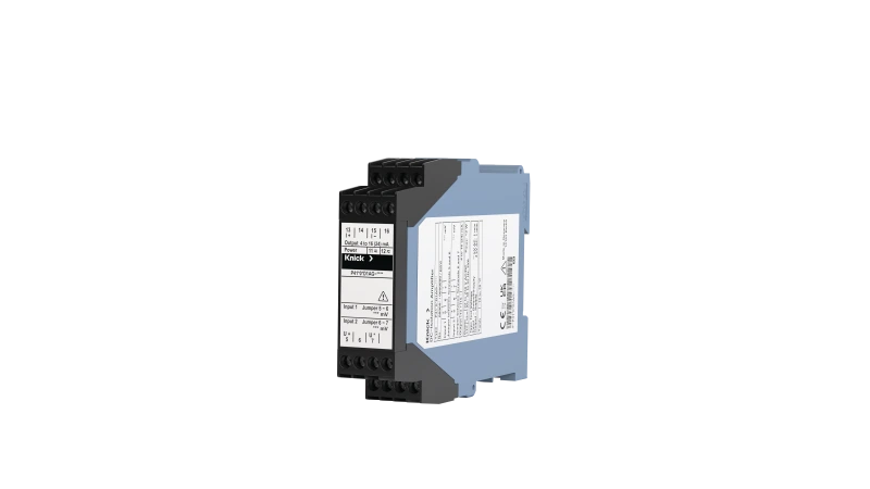
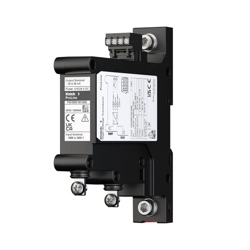
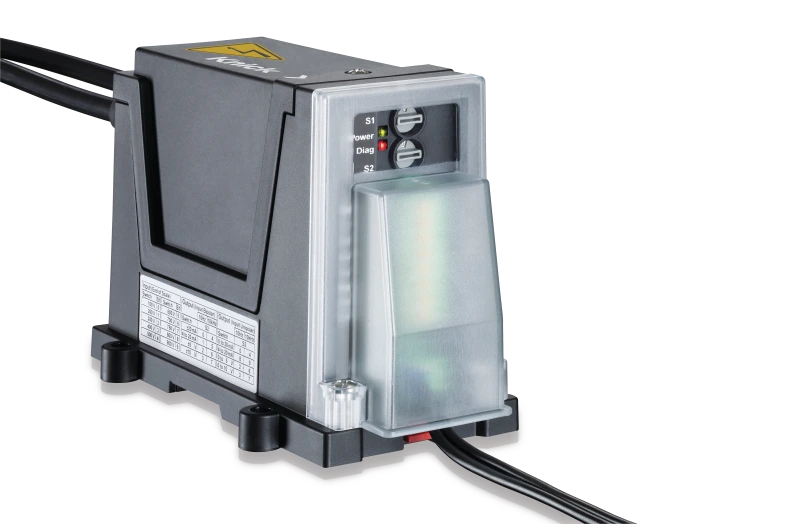
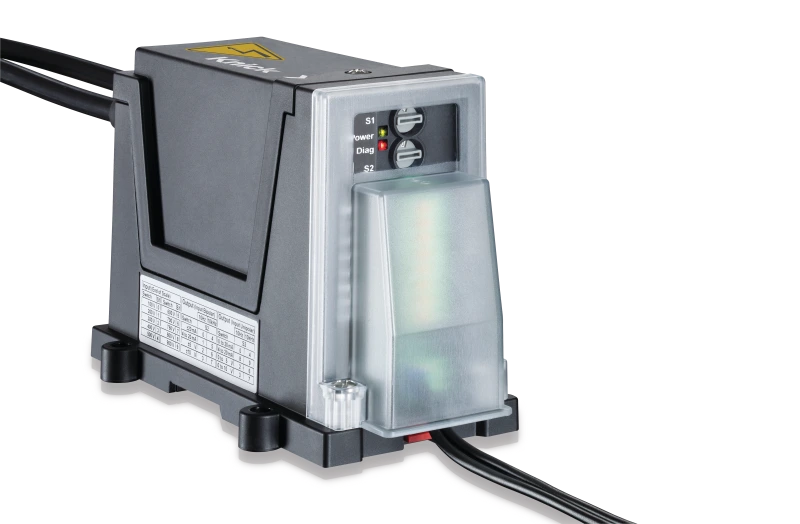
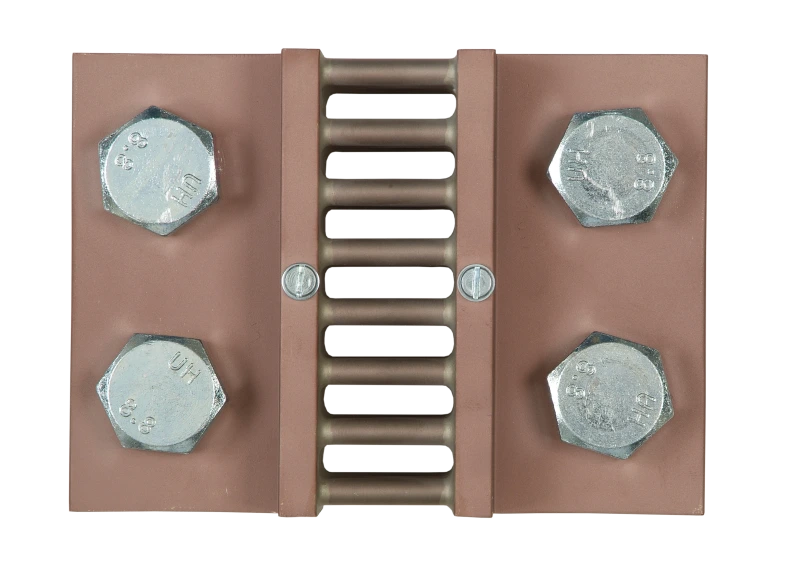
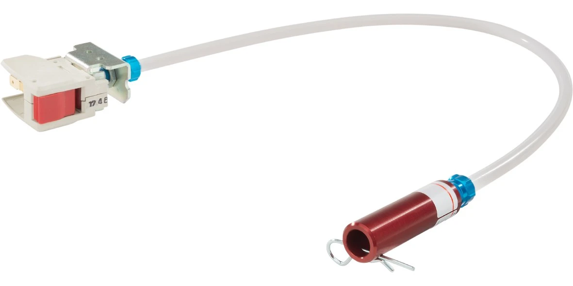
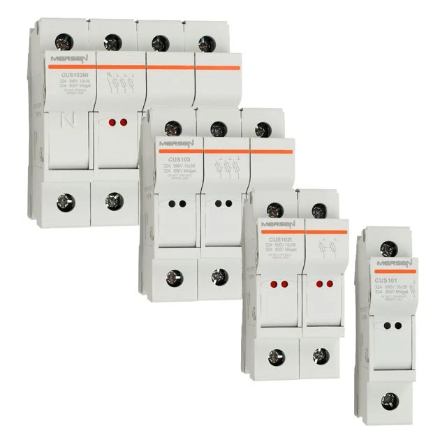
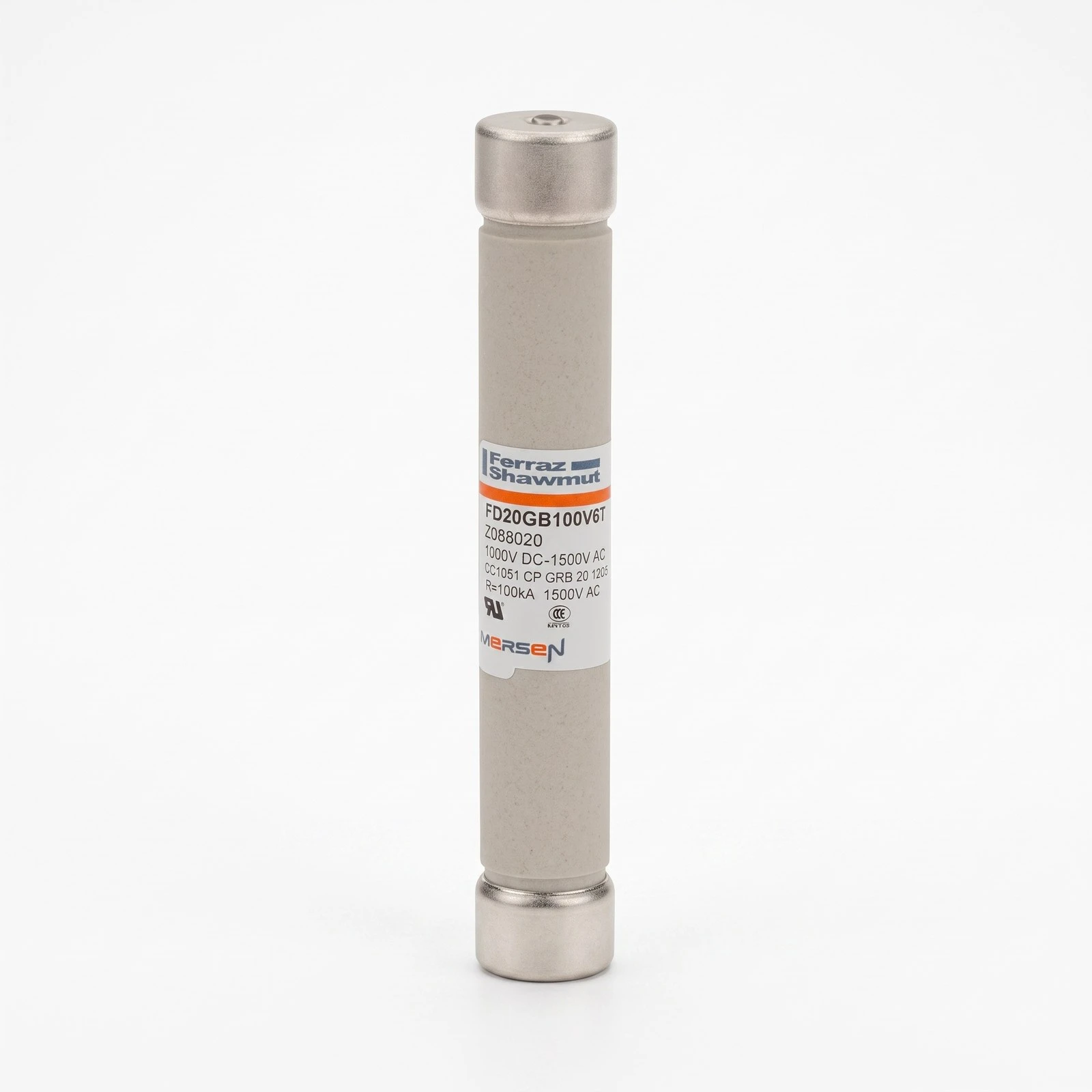
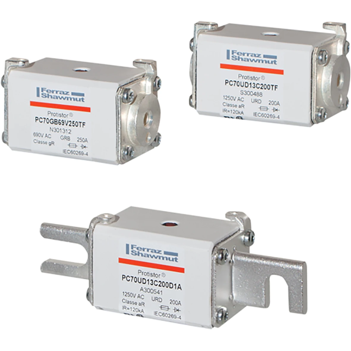
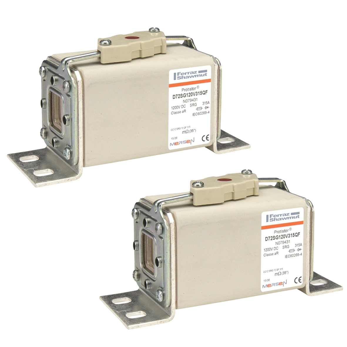
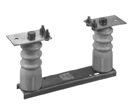
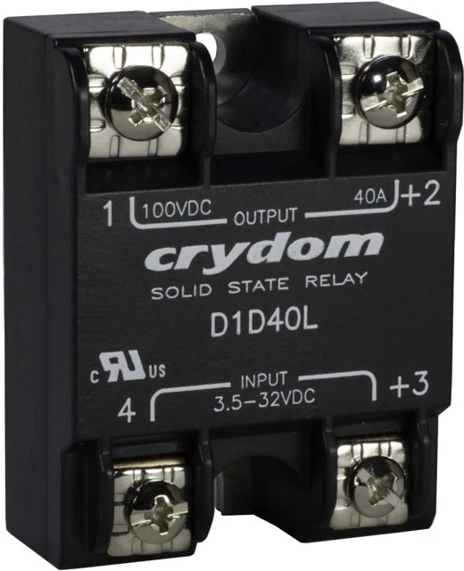
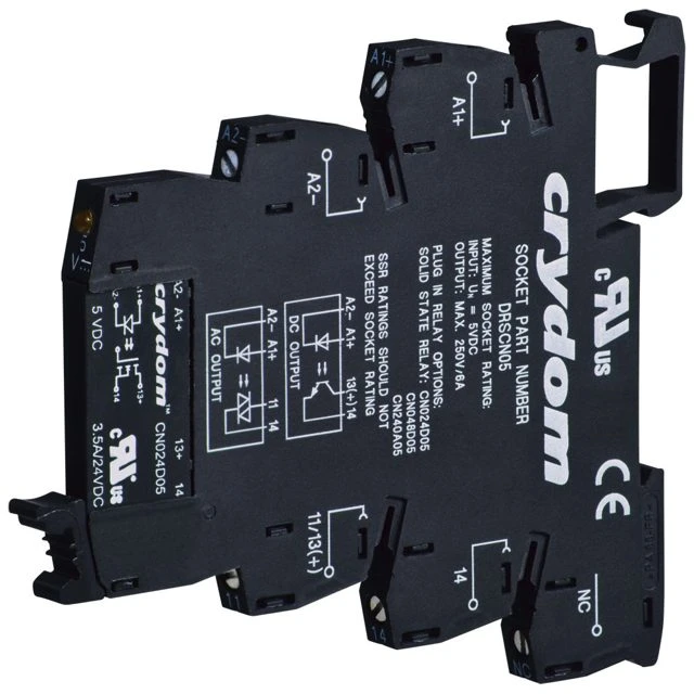
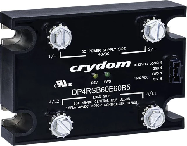
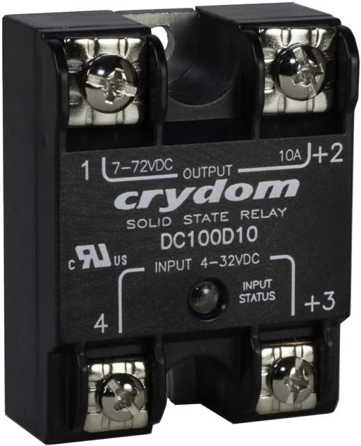
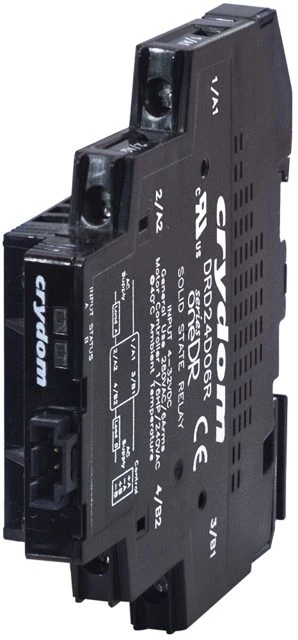
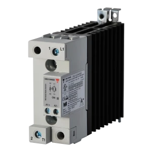
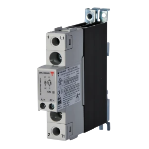
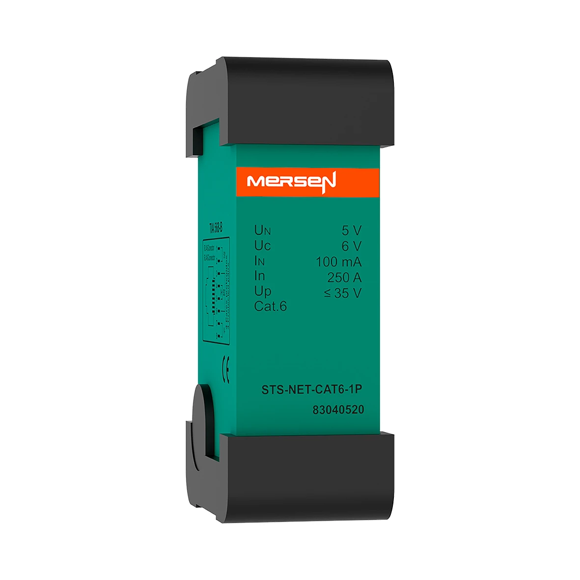
Equipment used in this area includes: hydraulic-magnetic and electronic circuit breakers for 24/110 V DC circuits, high-power and remotely operated main circuit breakers, DC contactors and solid-state relays, high-speed fuses and traction fuse bases, voltage and current transducers with isolation rated to 3.6 kV and above, signalling and interface relays, power supplies and buffer modules, terminal blocks, connectors and 19-inch enclosures designed for onboard applications.





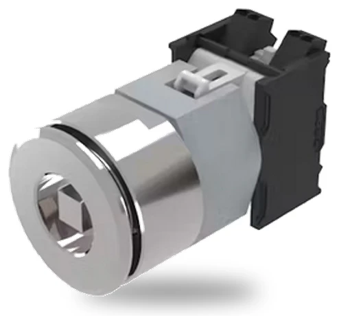
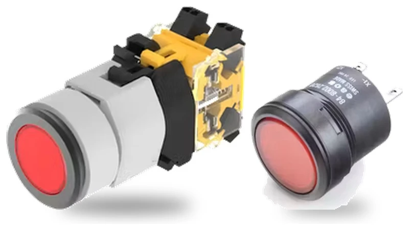
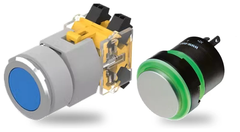
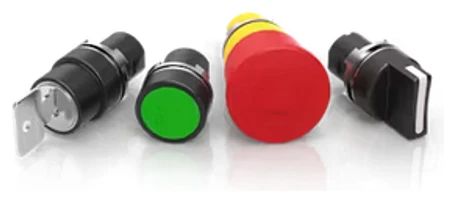
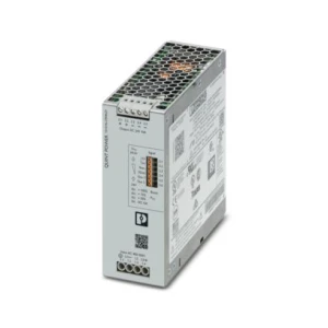
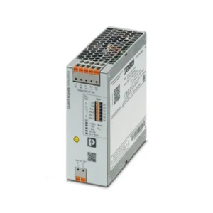
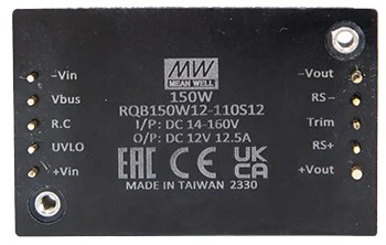
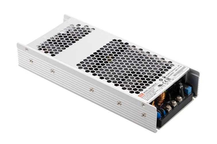



Selection criteria for this area:
The vehicle circuit breaker should limit the fault current below the substation breaker setting before the latter operates. The condition is that the current limited by the onboard breaker must remain below the substation setting, while the limiting rate of current rise is equal to (substation setting − vehicle setting) / vehicle-breaker current-limiting time. Vacuum breakers with a limiting time of about 2 ms provide selectivity with a setting difference of about 2 kA up to a current-rise rate of 1 kA/ms - which covers most Polish railway lines.
Their tripping depends on current and fluid flow in the damping mechanism rather than on heating a bimetal element, so the characteristic remains stable over the cabinet's full temperature range. In a vehicle, where cabinet temperature may vary by several tens of degrees, a thermal breaker would require trip-setting correction.
The onboard network is typically 110 V DC and 24 V DC, and passenger coaches may also use 3×400 V AC and 230 V AC from converters. Control circuits in conventional locomotives operate at 110 V DC. EN 50155 defines the voltage ranges, tolerances and permissible interruptions for electronic equipment.
DC current does not naturally cross zero, so the contactor must force arc extinction itself - using an arc chute, magnetic blowout or vacuum - and its switching capacity depends on the circuit time constant. Requirements for electrotechnical components used on rolling stock are covered by the IEC 60077 series; an industrial contactor according to IEC 60947-4-1 does not provide the same declaration.