Trackside power and automation cabinets

Trackside power and automation cabinets

Along the railway line, between substations and signal boxes, there are hundreds of cabinets and containers that operate without local supervision: automatic block signalling huts beside signals, automatic level-crossing warning-system containers, transformer points of the non-traction auxiliary power line, disconnector-drive and remote-control boxes, and point-heating supply cabinets. They are supplied from substations by the 15, 20 or 6 kV non-traction auxiliary power line, stepped down at transformer points to 0.4 kV, while SBL automatic block and SSP level-crossing equipment operates at 230 V.

A common feature of these facilities is the requirement for fail-safe behaviour during faults and loss of power: a track circuit indicates occupancy whenever an abnormal condition occurs, a de-energized track relay means “occupied”, level-crossing barrier drives close automatically after a power failure, and opening an SSP cabinet is reported to a staffed control post. These installations must also cope with an outdoor environment without air conditioning, proximity to the 3 kV DC overhead contact system with its overvoltages and stray currents, and track circuits carrying signalling voltages of approximately 2–12 V alongside power circuits.

Equipment used in this area includes: power supplies and DC/DC converters, uninterruptible power supplies and buffer modules, surge protection devices for power and signalling circuits, DIN-rail circuit breakers with tripping characteristics independent of ambient temperature, interface and signalling relays, solid-state relays for point heaters, terminal blocks, fibre-optic boxes, wall-mounted and pole-mounted enclosures, and outdoor cabinets.

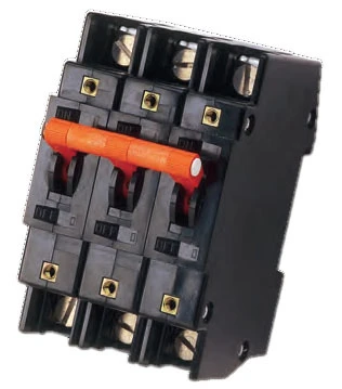
Airpax hydraulic-magnetic circuit breakers

Sensata
Hydraulic-magnetic circuit breakers - DIN rail
Airpax IALR/IULR/IELR DIN-Rail Circuit Breaker (0.05–100 A)
Sensata
Hydraulic-magnetic circuit breakers - DIN rail
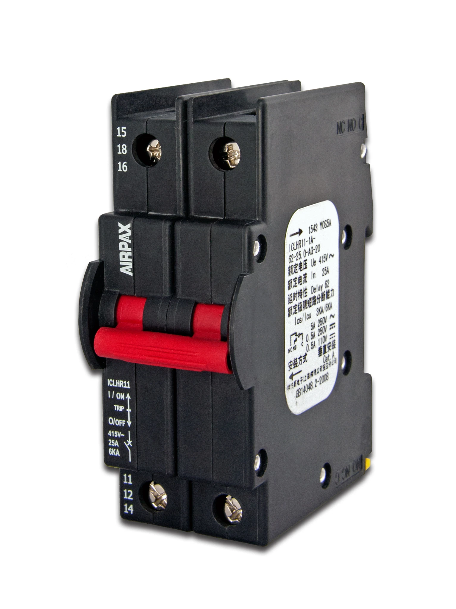
Airpax ICL/ICLR DIN-Rail Hydraulic-Magnetic Circuit Breaker (0.5–63 A, up to 415 VAC)
Sensata
Remote-controlled circuit breakers
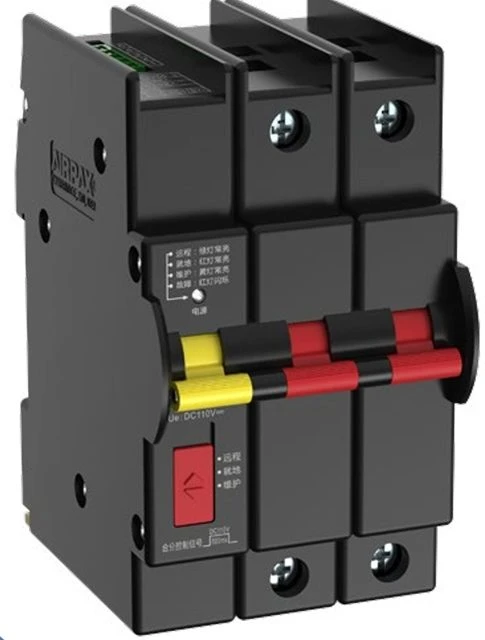
Airpax ICLR + ROCB Remote-Control Circuit Breaker
Sensata
Hydraulic-magnetic circuit breakers - panel mount
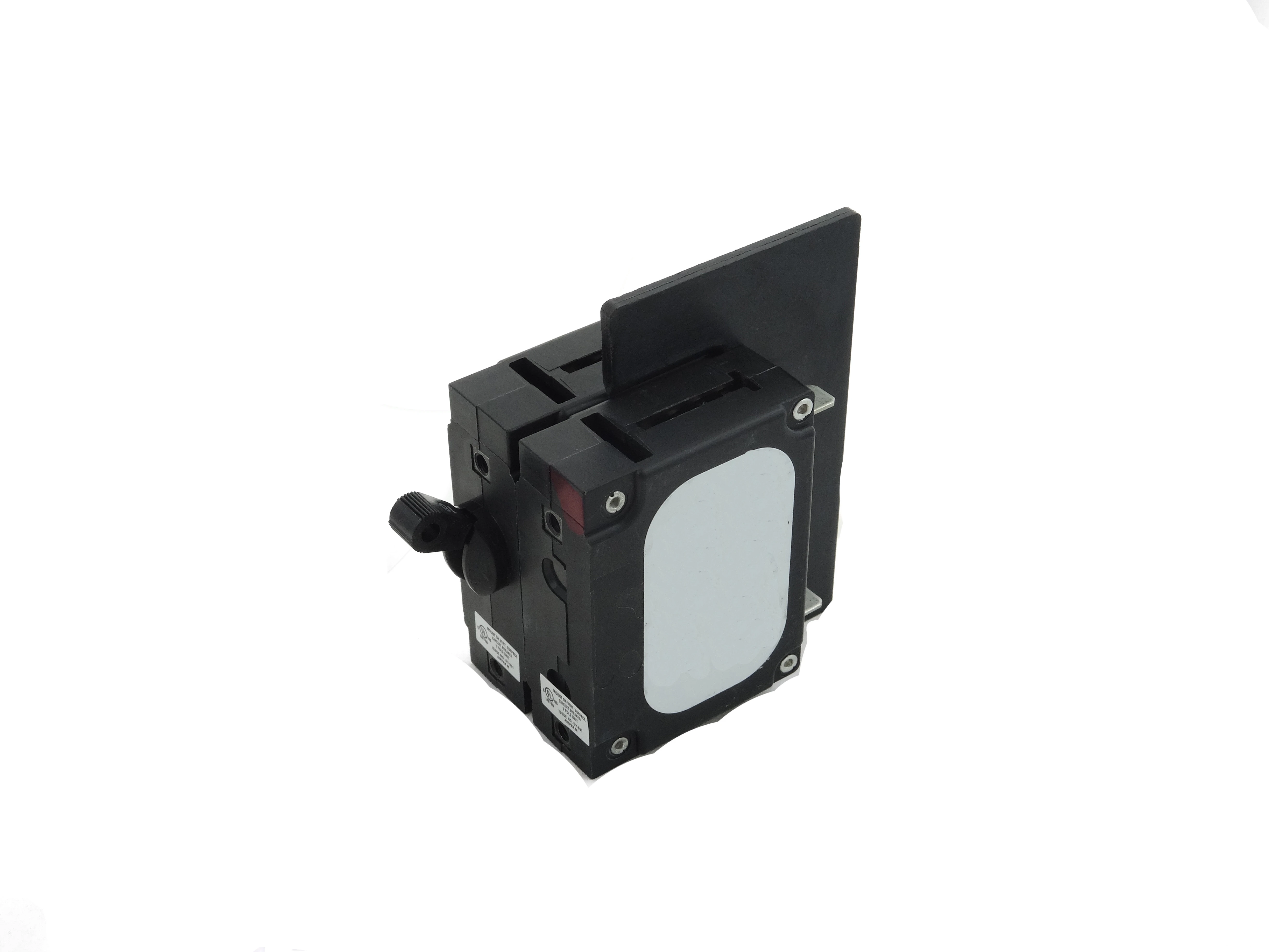
Airpax LEJ/LEJA Hydraulic-Magnetic Circuit Breaker (up to 30 A/240 VAC, 20 A/277 VAC)

Connectors

Phoenix Contact
CLIPLINE complete DIN-rail terminal blocks
CLIPLINE complete - DIN-Rail Terminal Blocks (PT/PTV/ST)

Contactors and relays

Hengstler
Signal relays (4/6 contacts)
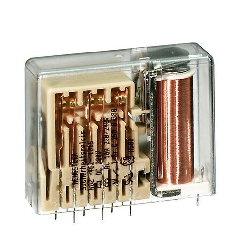
H-462 - Signal Relay (4 or 6 contacts)
Hengstler
Signal relays (8/10 contacts)
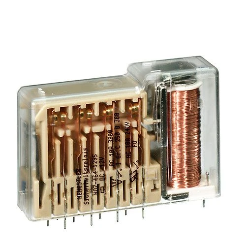
H-464 - Signal Relay (8 or 10 contacts)
Hengstler
Flat relays (4-10 contacts)
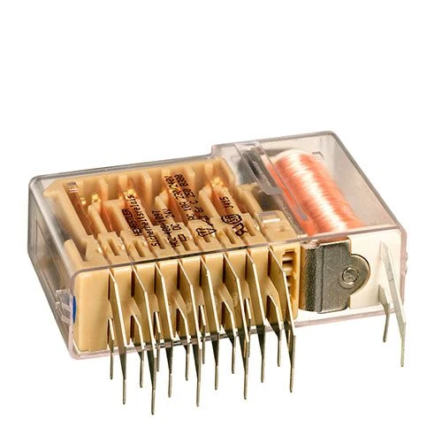
H-466 - Flat Relay (4–10 contacts)
Hengstler
Low-profile PCB relays (7 contacts)
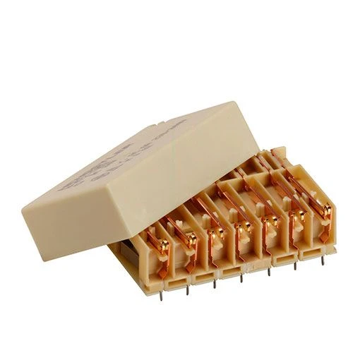
H-472 - Low-Profile PCB Relay (7 contacts)
Hengstler
Low-profile PCB relays (5 contacts)
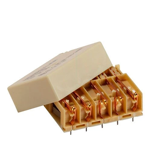
H-473 - Low-Profile PCB Relay (5 contacts)

Enclosures and cabinets

nVent Schroff
Rugged IP67 enclosures
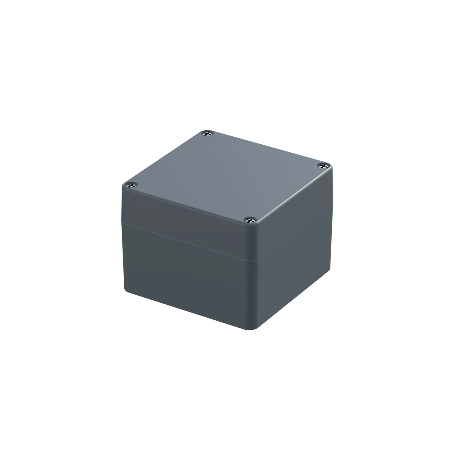
Rugged IP67 Small Form Factor Enclosure - IP-PRO Alu EMC
nVent Schroff
Outdoor wayside cabinets
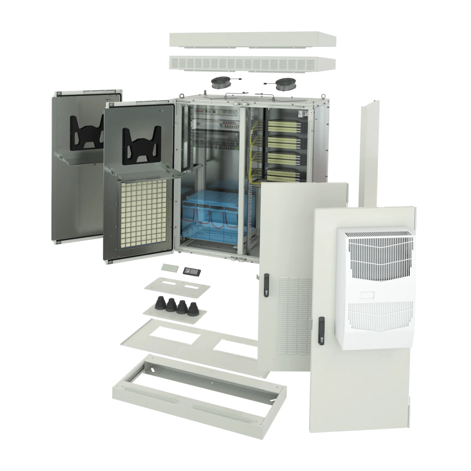
Wayside Outdoor Modular Cabinet
nVent Schroff
Wayside enclosures
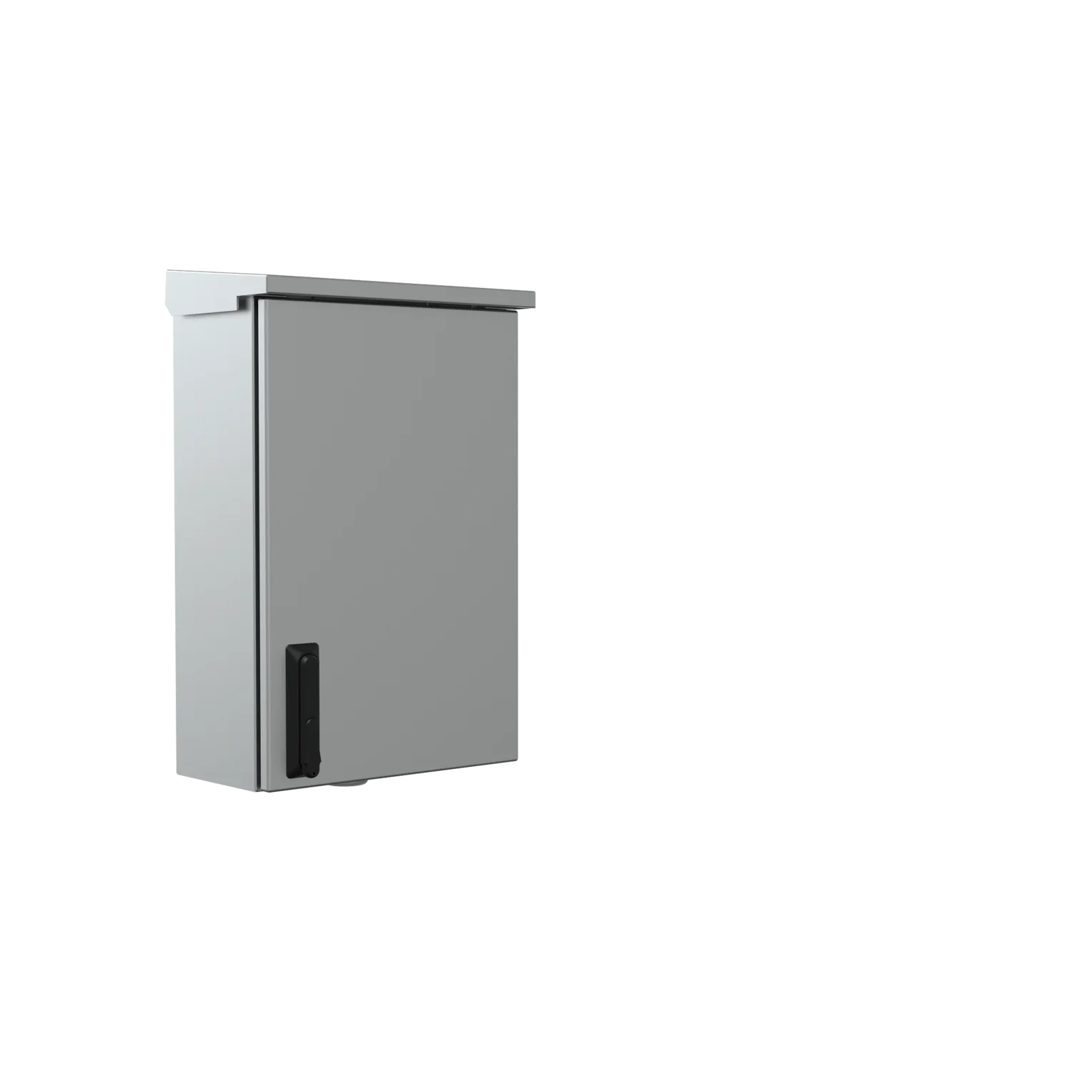
Wayside Wall-Mounted and Pole-Mounted Enclosures

Equipment protection circuit breakers

Phoenix Contact
Equipment circuit breakers
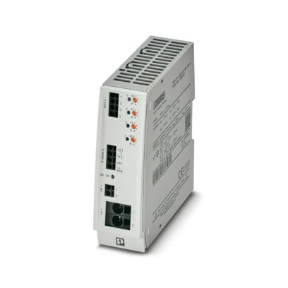
CBM E4 and E8 - Multi-Channel Circuit Breakers
Phoenix Contact
Equipment circuit breakers
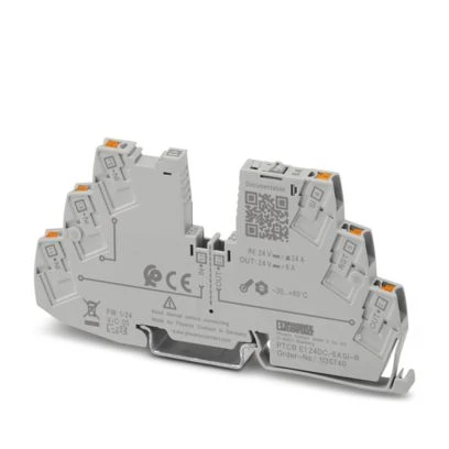
PTCB E1 - Electronic Circuit Breakers

Fibre optic boxes

Phoenix Contact
Fiber-optic distribution boxes
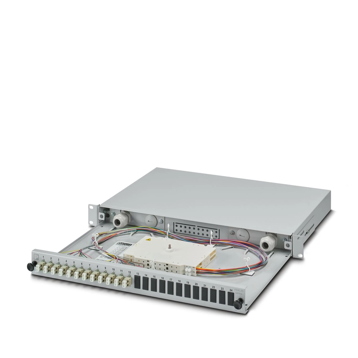
19" Rack-Mount Fiber Optic Boxes
Phoenix Contact
Fiber-optic distribution boxes
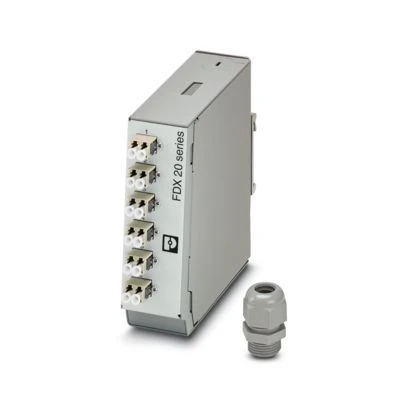
DIN-Rail Fiber Optic Boxes

Marking and labelling

Phoenix Contact
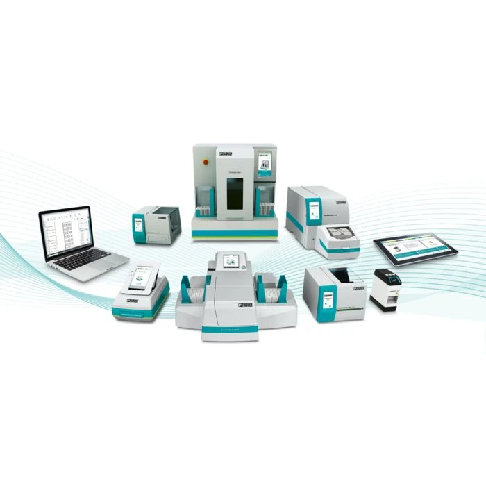
Marker printers
Marker Printing Systems
Phoenix Contact
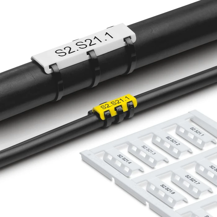
Cable markers for harsh environments
PATG HF and Metal Labels
Phoenix Contact
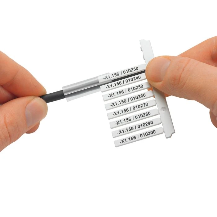
Markers for terminal blocks, wires and devices
UniCard Markers (UC / UCT)
Phoenix Contact
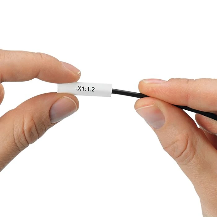
Wire and cable markers
WMS-2 HF - Heat-Shrink Sleeves

Networking and cybersecurity

Phoenix Contact
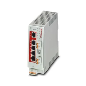
OT cybersecurity
FL MGUARD

Power supplies and converters

Phoenix Contact
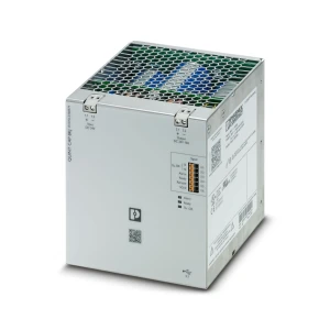
Buffer and redundancy modules
QUINT - Capacitor Modules
Phoenix Contact
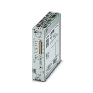
DC UPS power supplies
QUINT - Uninterruptible Power Supplies (UPS)
Phoenix Contact
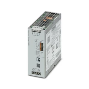
AC/DC switching power supplies
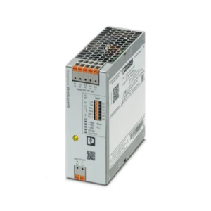
QUINT POWER AC/DC
Phoenix Contact
DC/DC converters
QUINT POWER DC/DC

Relays

Phoenix Contact
PLC-INTERFACE relay modules
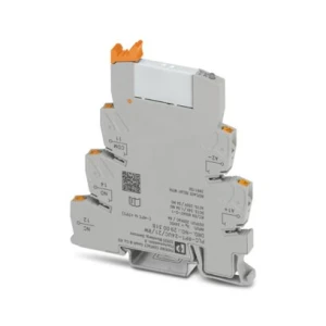
PLC-INTERFACE - Electromechanical Relays
Phoenix Contact
PLC-INTERFACE relay modules
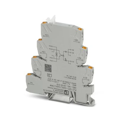
PLC-INTERFACE - Solid-State Relays

Sensors, transducers and measurement

Carlo Gavazzi
Current transformers
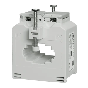
CTD / CTA Series
Carlo Gavazzi
Energy meters
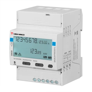
EM530 / EM540
Carlo Gavazzi
Power analyzers
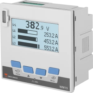
WM15
Carlo Gavazzi
Power analyzers
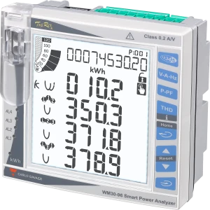
WM20 / WM30 / WM40

Short-circuit protection and fuses

Mersen
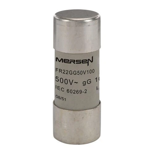
Auxiliary fuses
IEC Cylindrical Fuse Links
Mersen
Auxiliary DC fuses
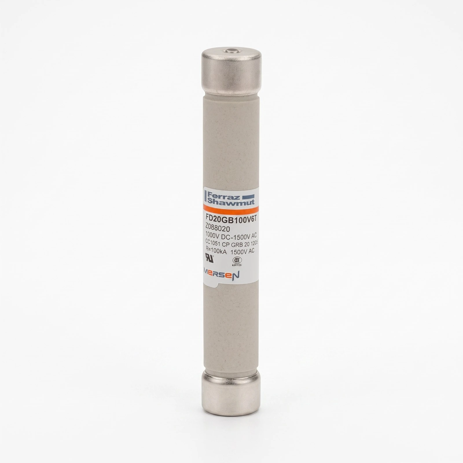
Protistor® Size 20x127 gR and 20x190 gRC 1000–1500 V DC

Solid-state relays

Sensata
AC solid-state relays - DIN rail
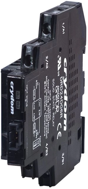
Crydom SeriesOne DR ATEX DIN-Rail Solid-State Relay (Zone 2)
Carlo Gavazzi
Solid-state relays
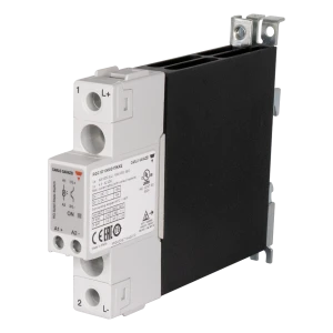
RGC (1-phase)
Carlo Gavazzi
Solid-state relays
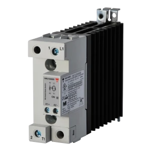
RGC2 / RGC3
Carlo Gavazzi
Solid-state relays
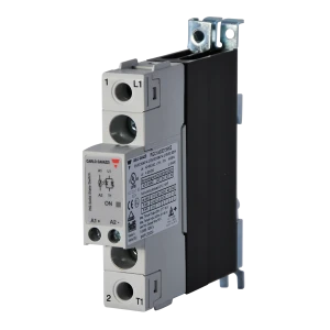
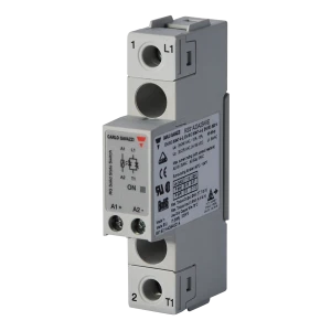
RGH
Carlo Gavazzi
Solid-state relays
RGS

Surge protection

Phoenix Contact
Surge protection devices (SPD)
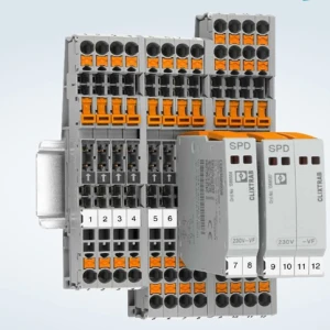
CLIXTRAB - Signal Circuit Protection
Phoenix Contact
Surge protection devices (SPD)
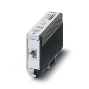
Data Line and Antenna Line Protection
Phoenix Contact
Surge protection devices (SPD)
FLT-SEC - Power Supply Protection for Railway Facilities
Mersen
Surge protection devices (SPD)
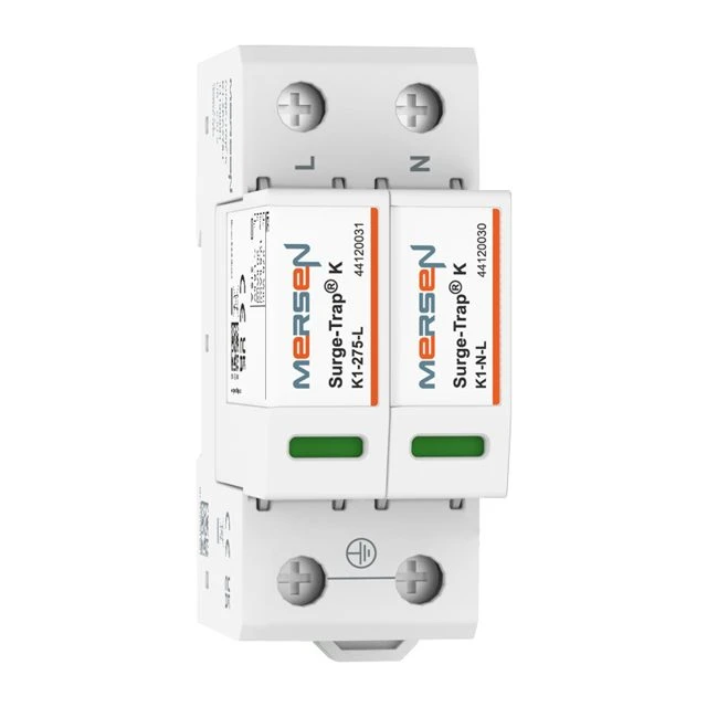
K Series SPD Type 1+2 / Type 2
Mersen
Surge protection devices (SPD)
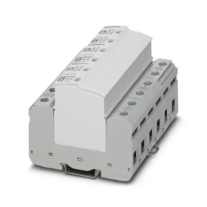
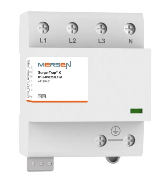
Surge-Trap® K1H-4PG255LF-M (SPD Type 1+2, 3+1, 230/400 V AC)

Tools

Phoenix Contact
Hand tools and automatic tooling
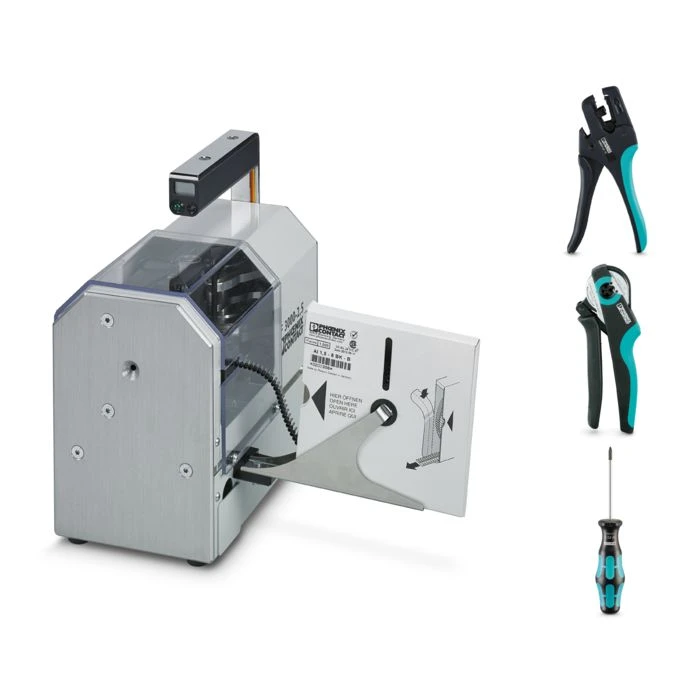
Assembly Tools and Automatic Machines

Selection criteria - Trackside power and automation cabinets

Selection criteria for this area:

  • Temperature range without air conditioning - a trackside cabinet experiences both frost and solar heating; equipment is selected for the full range, with hydraulic-magnetic trips preferred over thermal trips.

  • Multi-stage surge protection - SPDs on the 230/400 V supply (type 1+2 or type 2), separately on signal circuits and data lines; energy coordination between stages; earthing consistent with the bonding system.
  • Track-circuit separation - 2–12 V AC signal circuits are located next to 230 V circuits and traction current; galvanic isolation, shielding and proper cable routing are required.
  • Continuity of power supply - UPS or buffer module for controllers and communications; backup time is determined by the travel time of maintenance crews.
  • Fail-safe principle - track relays and level-crossing barrier control relays with forcibly guided contacts; logic based on “no signal = restrictive state”.
  • Remote diagnostics - status of power supplies, SPD operation and cabinet opening reported to the control post; relays with auxiliary contacts and SPDs with remote indication.
  • Point heating - resistance heaters switched cyclically; solid-state relays with load monitoring detect a failed heater before the switch blade freezes.
  • Enclosure - degree of protection, condensate drainage, vandal resistance and ventilation; door-opening monitoring.

Technical questions

How are trackside devices powered?

From the non-traction auxiliary line (LPN) at 15, 20 or 6 kV, which runs along the route from a traction substation; at transformer points it is stepped down to 0.4 kV. The LPN supplies stations, stops, signals, automatic block cabinets, level-crossing barriers and point heating. It has overcurrent, undervoltage and earth-fault protection, plus backup supply from the neighbouring substation.

How does a track circuit work and why is it “fail-safe”?

A transformer in the cabinet reduces 230 V to about 10 V, and a track transformer further reduces it to about 2 V applied to the rails of an insulated section; the signal returns through the rails to a relay transformer (about 12 V) and the track relay. A vehicle axle shunts the rails, the relay drops out and indicates occupancy. Any abnormal condition - an open circuit, short circuit or loss of power - produces the same “occupied” state, so a failure cannot result in a permissive signal.

What timing requirements apply to automatic level-crossing warning systems?

The warning lasts at least 30 s (two half-barriers or category C) or 46 s (four half-barriers); barriers must not start lowering earlier than 13 s after the lights are activated, must close within 10 s, and at least 7 s must elapse between full closure and the train's arrival. Total closure time should not exceed 2 minutes.

What happens to a level-crossing barrier if power fails?

Drives equipped with an automatic release mechanism close the barriers automatically after loss of power; the barriers can also be lowered manually after the drive is released. The “closed” state is the safe state, so the control system must not require energy to reach it.