


Railway traffic control equipment is divided into station systems (relay and computer-based interlockings) and line systems (block systems, track-to-train equipment, remote control and level crossings). In a relay interlocking, relays are the main components, accompanied by transformers, resistors and rectifiers; critical buttons on the tile-type control panel are sealed or operation-counted, and an ammeter indicates the current drawn by point machines. In a computer-based interlocking, the field level consists of object controllers, concentrators and transmission loops installed in telecommunications cabinets, with an auxiliary control panel available in the event of a computer failure.
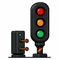
Requirements for telecommunications and IT systems at railway control posts are defined by PKP PLK instruction Ie-116: 230 V AC supply at −15/+10%, a 48 V DC battery with a grounded positive pole providing at least 8 hours of backup and a 10-year service life, equipment operating range of 43–57 V DC, redundant rack-mounted power supplies, MTBF of at least 10,000 h, 15 years of operation and service support, room temperature of +5…+35 °C (0…+45 °C at the limits), EMC immunity in accordance with PN-EN 50121-4 and PN-EN 61000-6-2, and surge protection at the distribution frame for all copper links. Signals are supplied from 230 V, stepped down to 110 V in the relay room and to 12 V in the signal head; the red aspect has a separate transformer, and lamp failure is monitored by a repeater on the control panel.
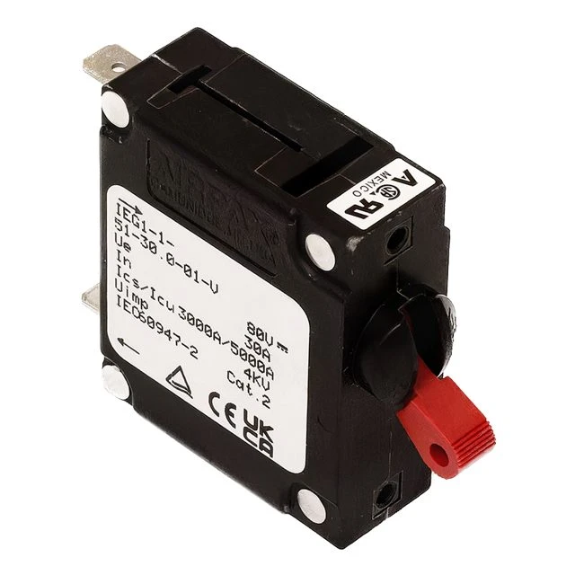
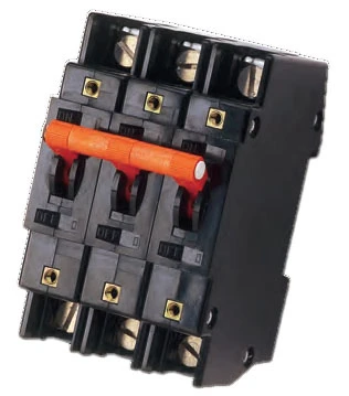
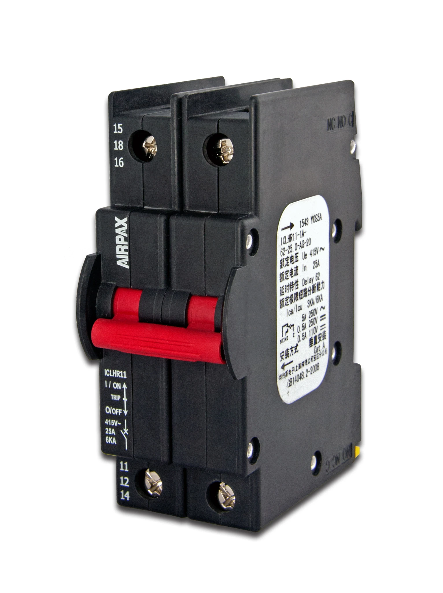
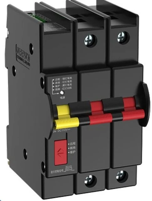
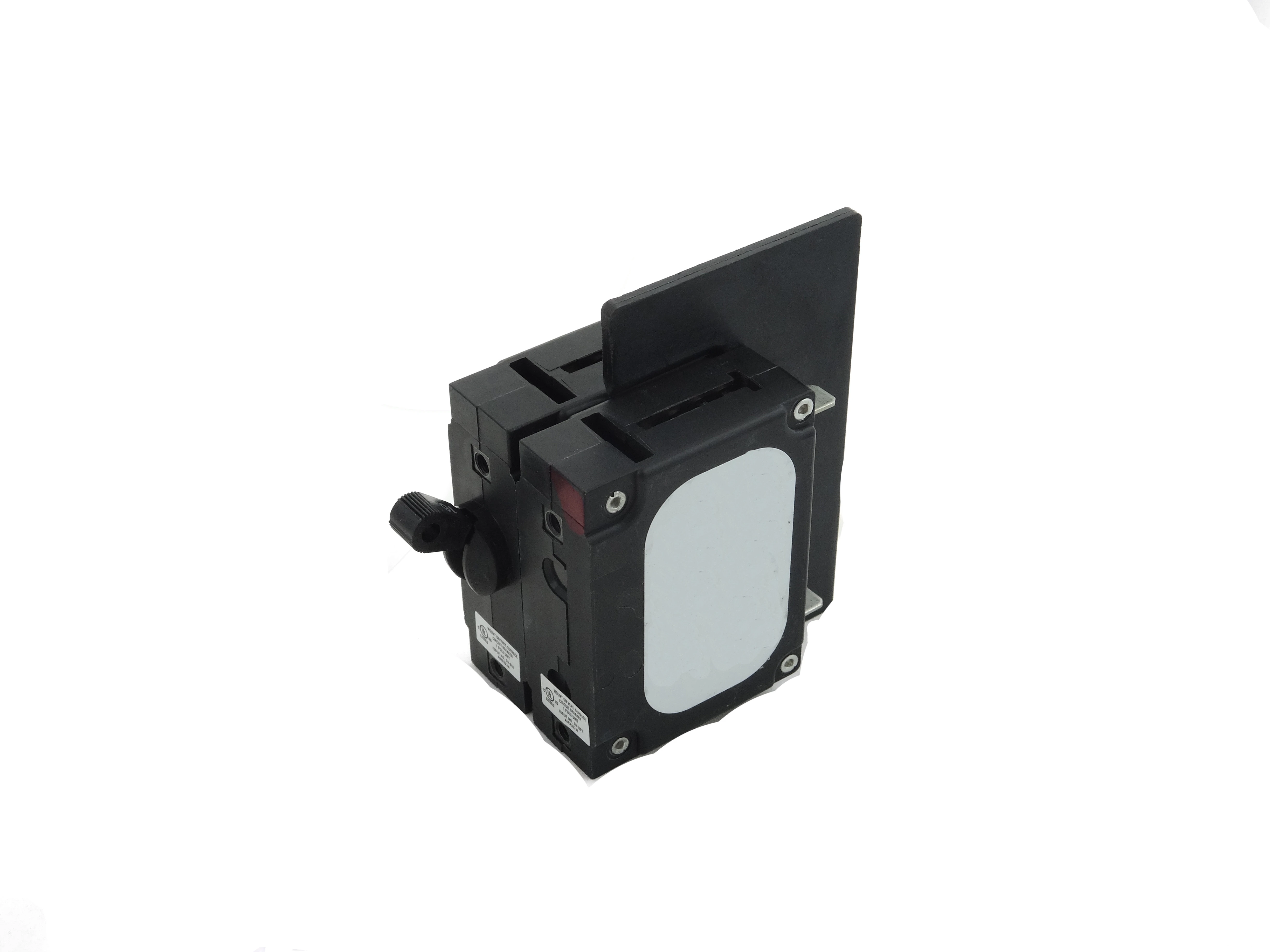
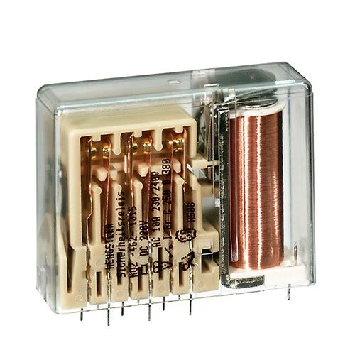
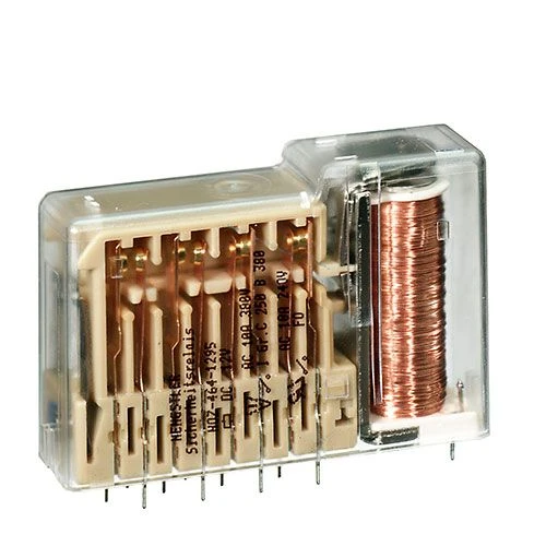
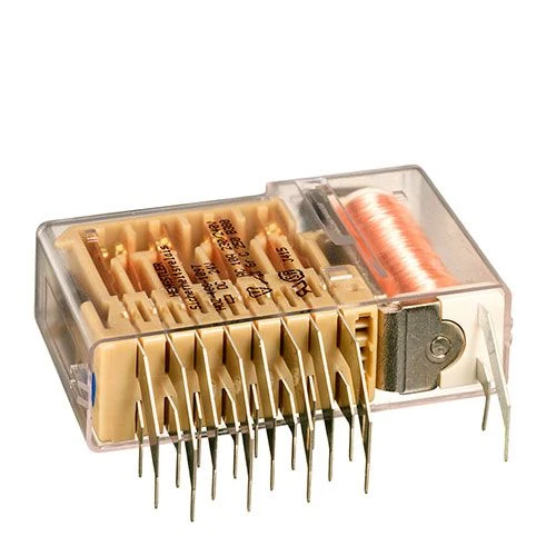
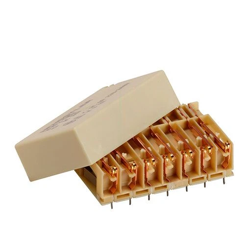
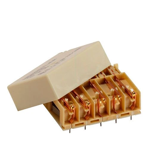
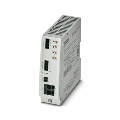
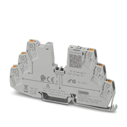
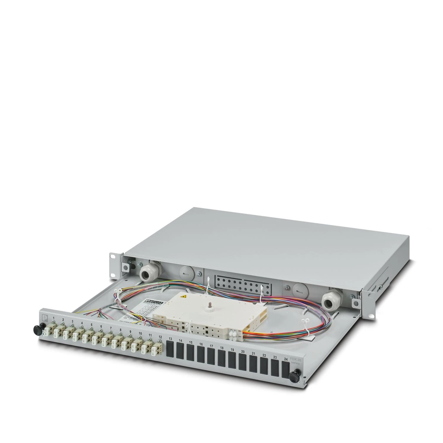
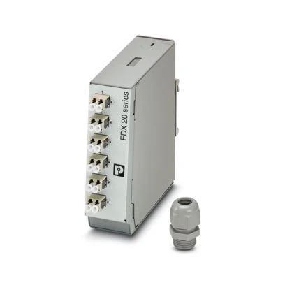
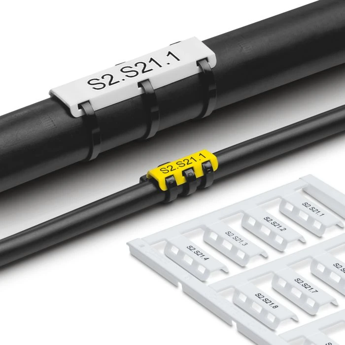
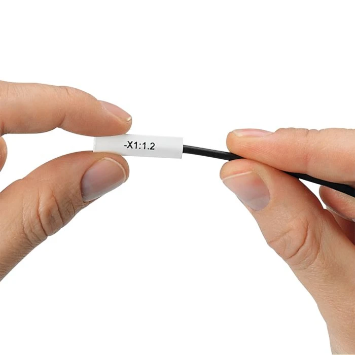
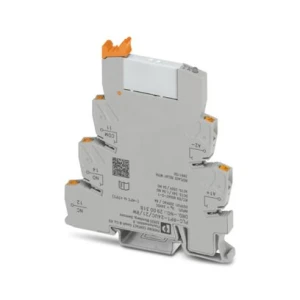
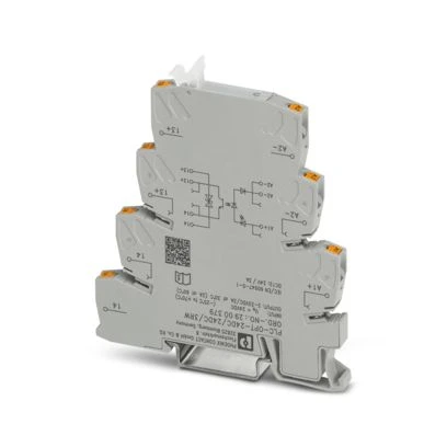
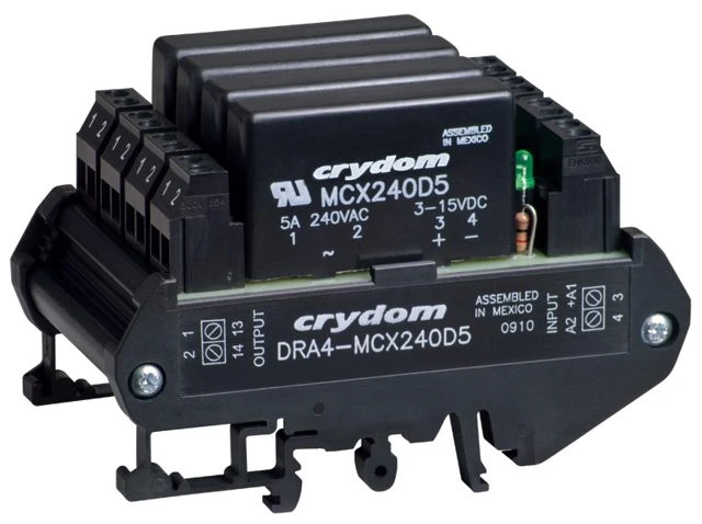
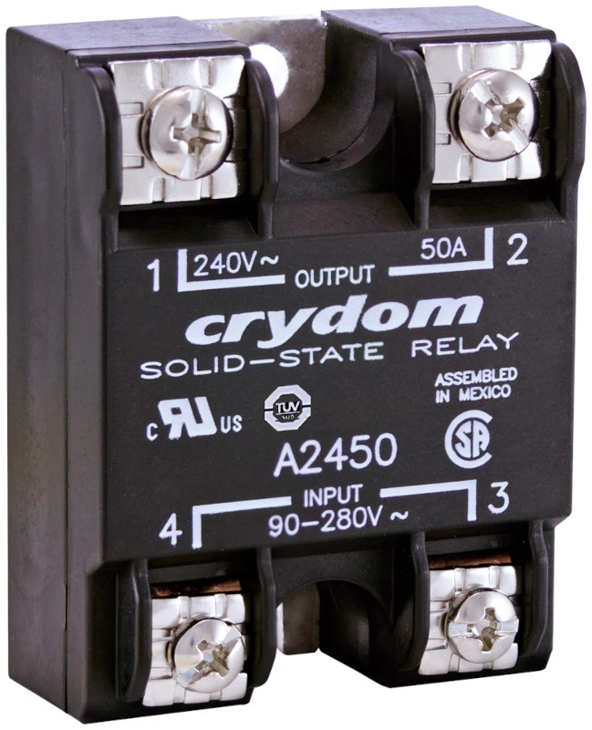
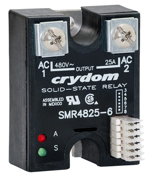
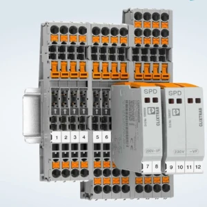
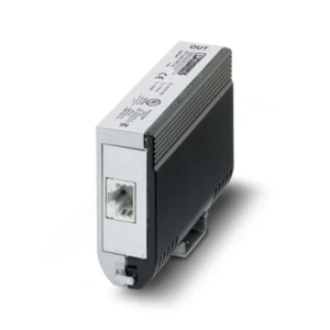
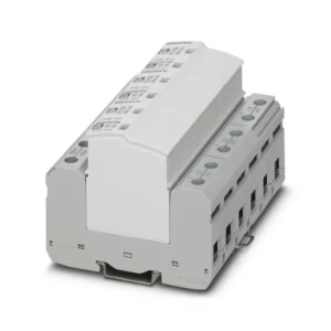
Equipment used in this area includes: signalling and interface relays with a large number of contacts, protection for 48 V DC and 230 V AC circuits, surge protection devices for power, signalling and data circuits, power supplies and uninterruptible power supplies, solid-state relays with circuit monitoring for signals, 19-inch cabinets and enclosures with enhanced EMC performance, fibre-optic boxes, terminal blocks and marking systems.




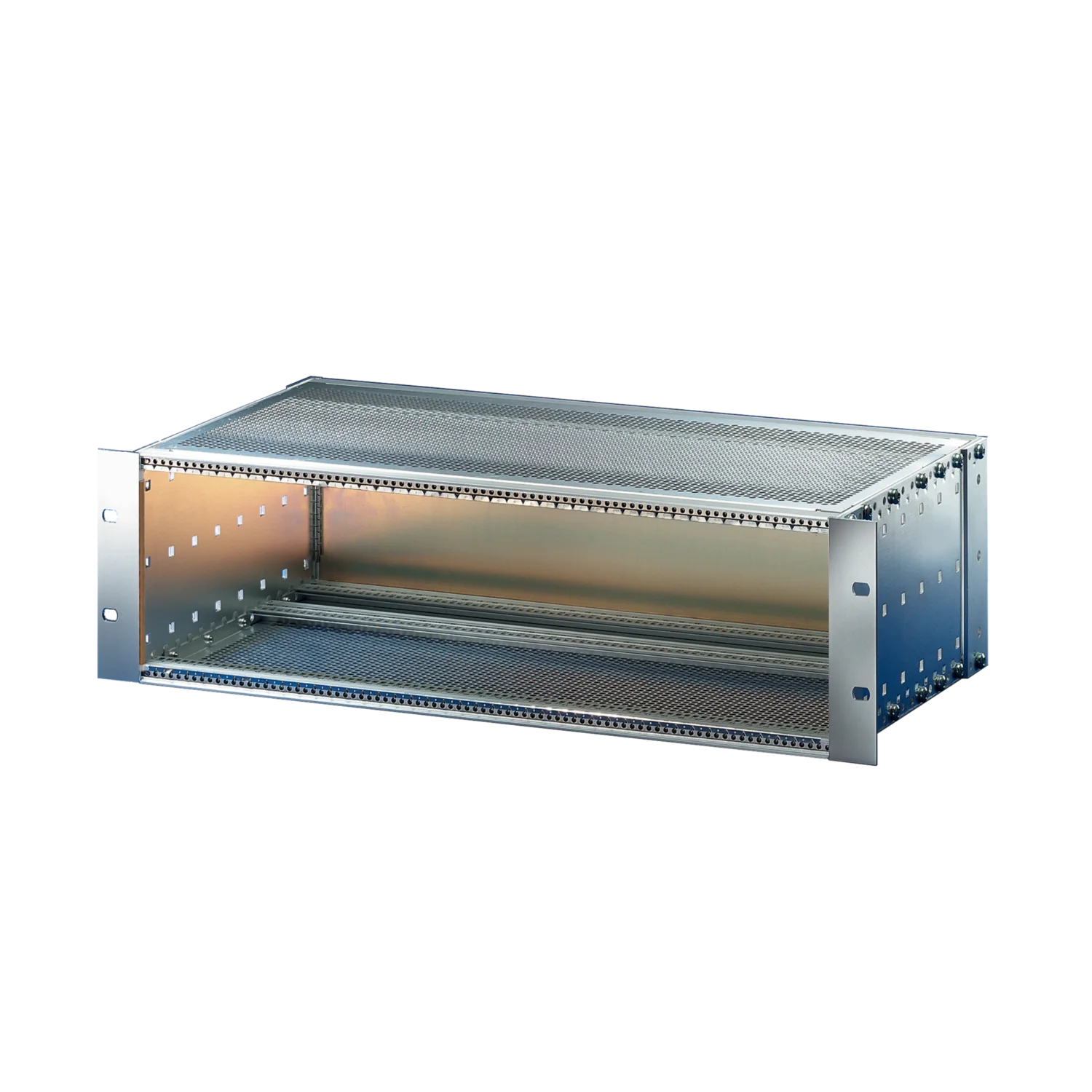
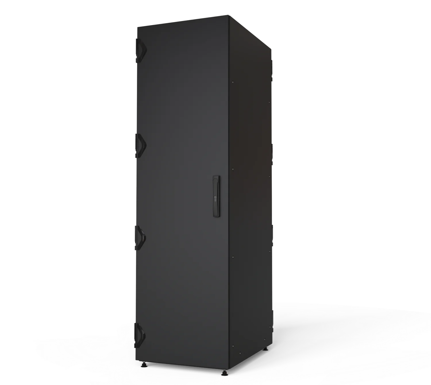
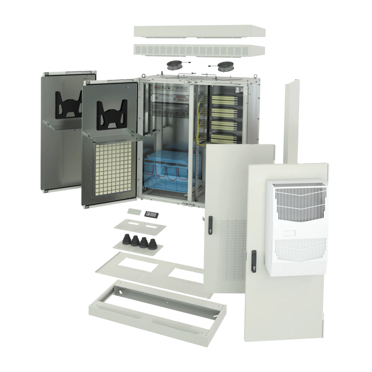
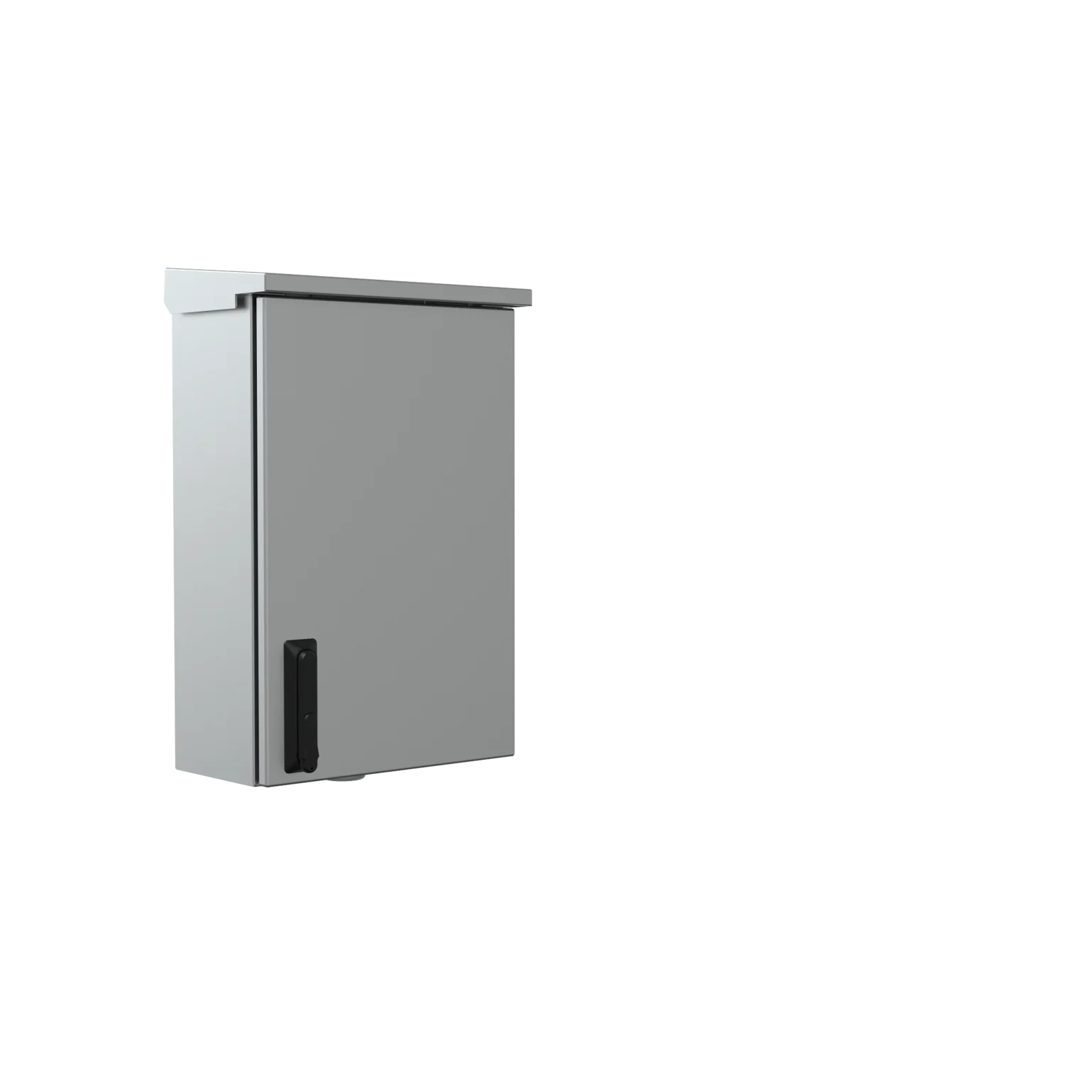
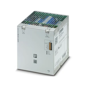
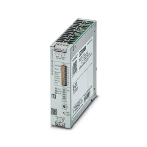
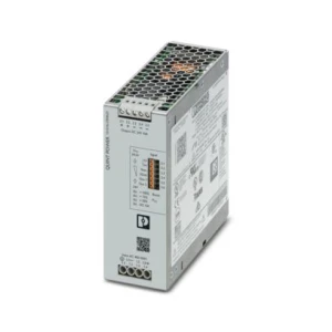
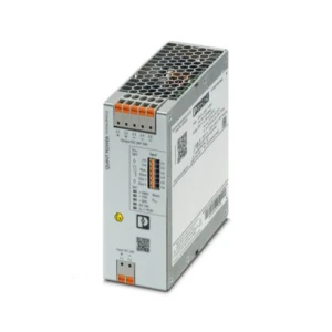
Selection criteria for this area:
This is required by instruction Ie-116 for railway traffic-control telecommunications systems. Earthing the positive pole means that the working conductor is negative with respect to earth - protective devices, SPDs and isolators must be selected for this polarity - equipment designed for a system with the negative pole earthed operates here under reversed conditions.
The main 24 W lamp and the 12 W standby lamp are supplied with 12 V AC from a transformer in the signal head; failure of the main lamp dims the repeater on the control panel, while failure of the standby lamp extinguishes it. In automatic block signalling, failure of the red aspect causes the preceding signal to display “Stop”. LED light sources are covered by instruction Ie-123.
It operates in interlocking circuits where contact state determines whether a permissive signal may be displayed; it requires forcibly guided contacts (a normally open and a normally closed contact cannot be closed at the same time), a large number of contacts, endurance measured in millions of cycles at low currents, and resistance to vibration and traction-system interference. A standard industrial relay does not declare these characteristics.
According to Ie-116: enclosed rooms, +5…+35 °C and 30–75% relative humidity in continuous operation; a marginal mode of 0…+45 °C and 20–80% is permitted for a maximum of 24 continuous hours and 240 hours per year. Trackside equipment has different requirements - Ie-116 does not cover outdoor devices.