


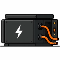
A static converter supplies the entire onboard network from the 3 kV DC circuit: 3×400 V AC for auxiliary drives and air conditioning, 110 V DC and 24 V DC for control, lighting and battery charging, and 230 V AC for sockets. At its input it has an HV fuse and a soft-start circuit with a resistor and contactors, followed by a filter choke, a DC/DC converter with an intermediate voltage (600 V DC in the example) and an inverter. A vehicle has at least two converters with reserve capacity and a voltage changeover contactor; the converters require cooling and are sensitive to disturbances from the traction supply.
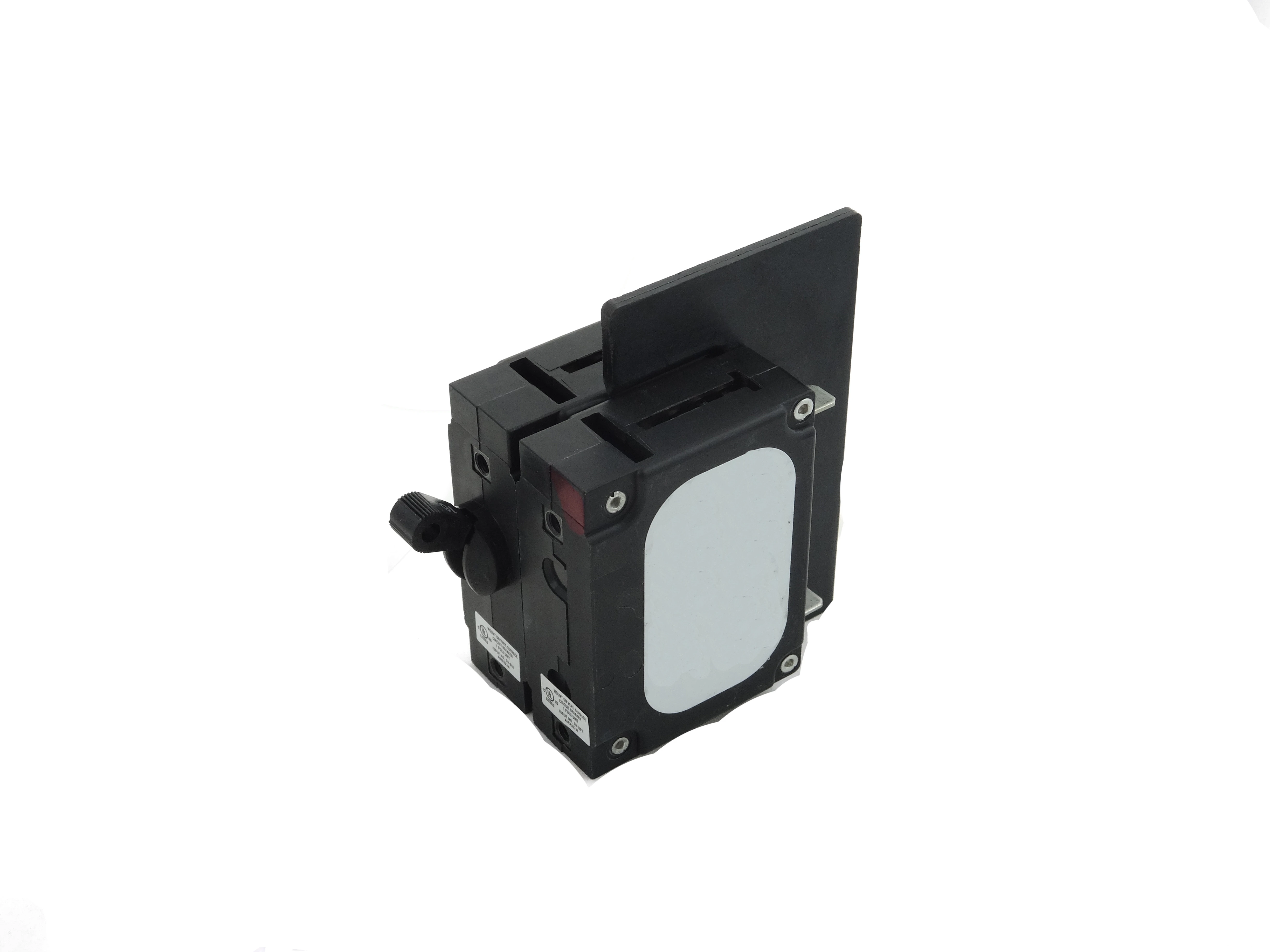
The onboard battery is the source that must operate when nothing else does: it supplies the auxiliary pantograph compressor, line-voltage measurement system, high-speed circuit breaker control, CA/SHP systems, magnetic track-brake coils and emergency lighting. It must be connected through fuses, with provision for permanent isolation by a manual disconnector at the battery box, and charged with cell-temperature monitoring. For example, in the EU06/EU07 locomotive (a classic 3 kV DC locomotive), the 96 V Ni-Cd battery (type 4G60H, 72 cells in 24 boxes) is protected by Bi-Wts 60 A fuse-links and a 63 A automatic circuit breaker serving as the battery isolator and mounted on a panel in the cab control desk. External 3×400 V supply through a standardized socket with pilot contacts is mandatory in new vehicles.
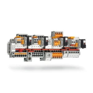
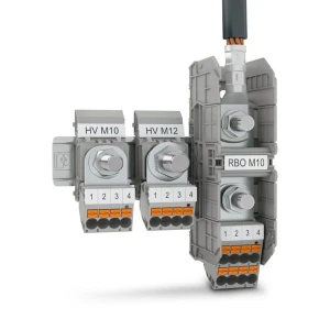
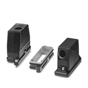
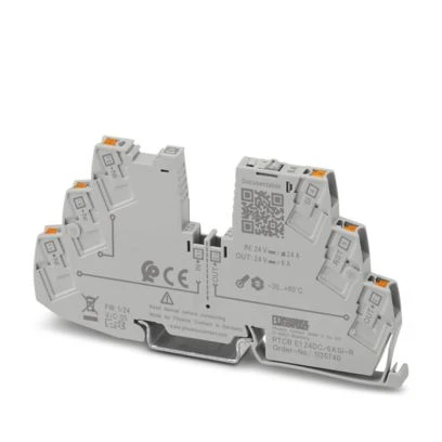
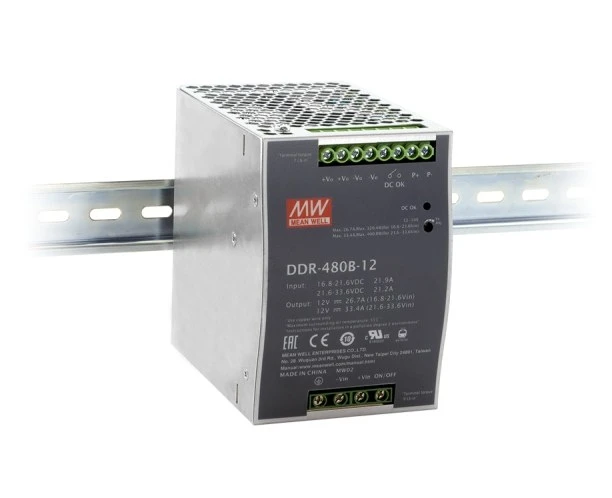
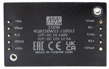
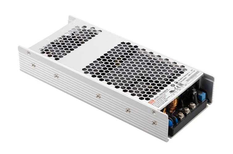
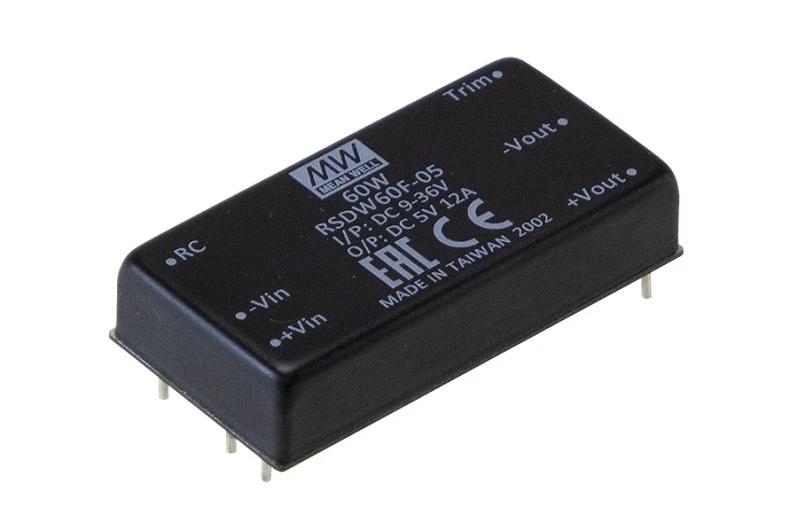
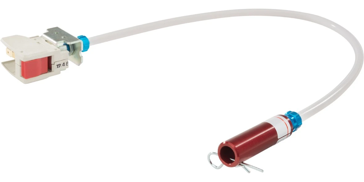
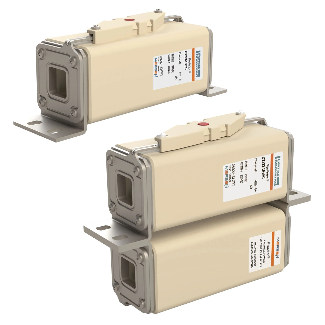
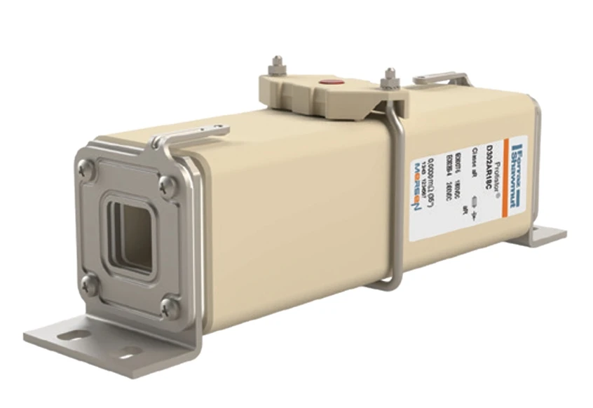
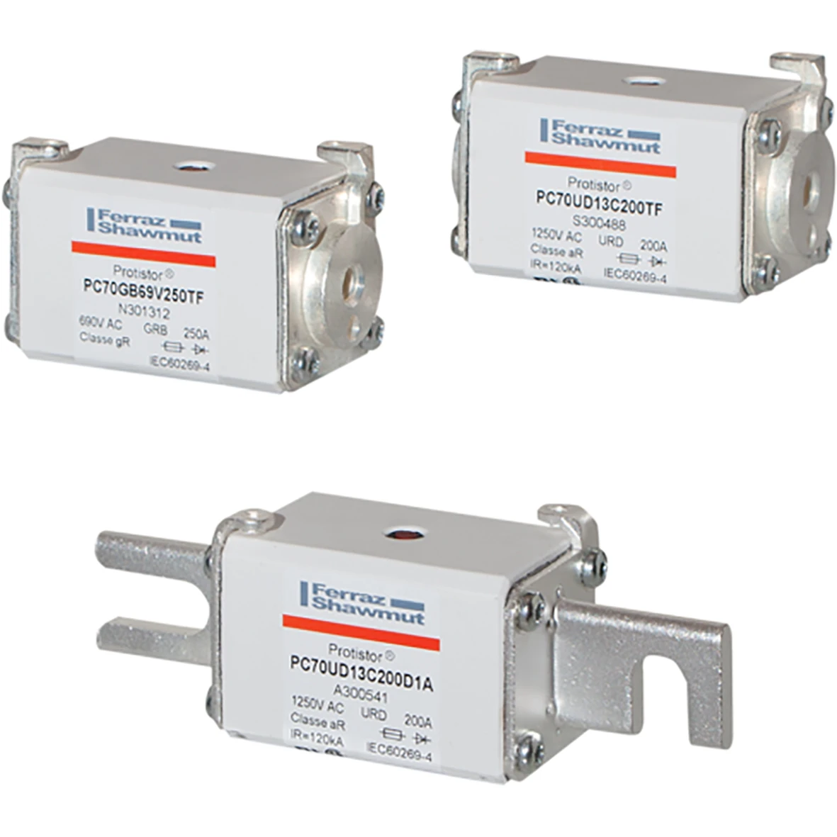
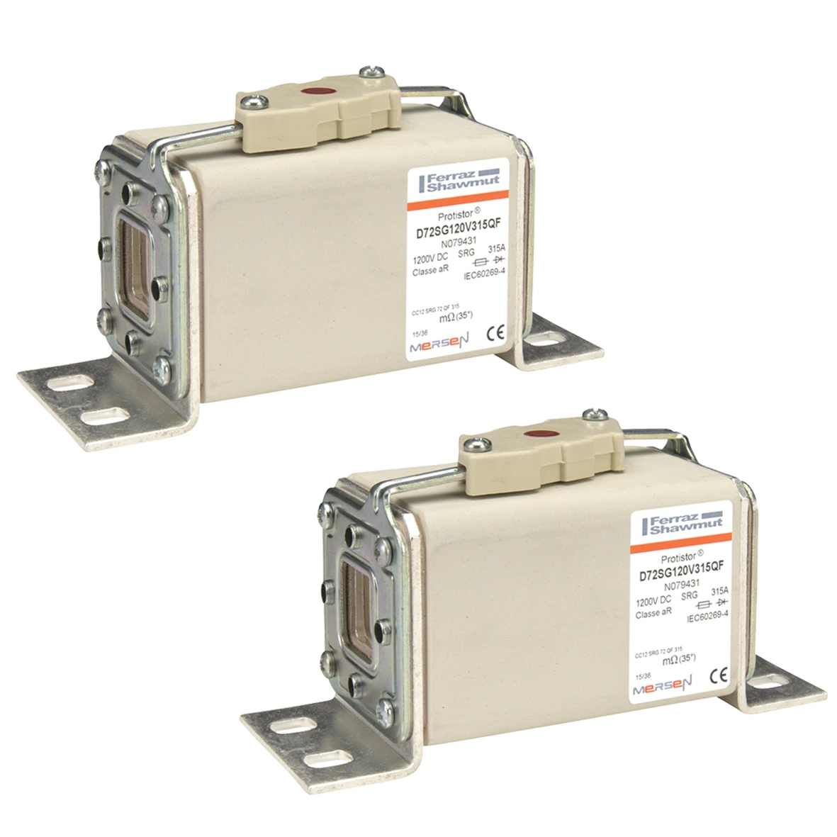
Equipment used in this area includes: high-speed DC fuse-links and traction fuse bases with trip indication, circuit breakers and disconnectors for the battery circuit, battery contactors and DC relays with undervoltage release, DC/DC converters and buffer power supplies, battery-box temperature sensors, high-current terminal blocks and external-power connectors.



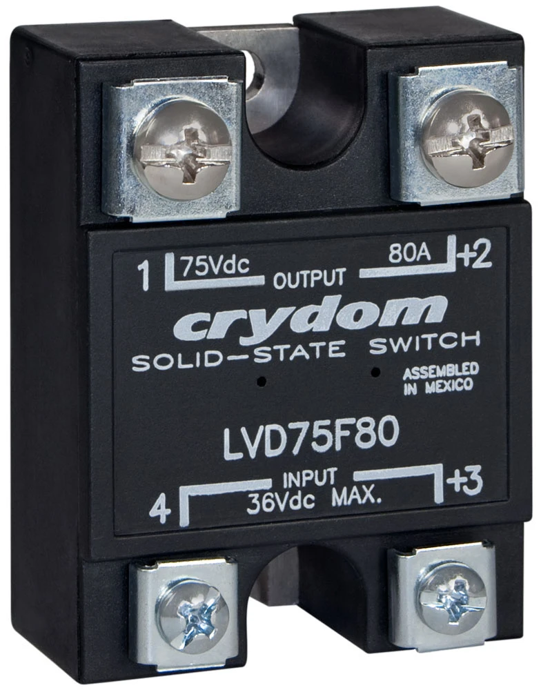
Selection criteria for this area:
Typically 3×400 V AC for auxiliary drives and air conditioning, 110 V DC or 24 V DC for control circuits and battery charging, and 230 V AC for sockets; some converters provide four outputs (24 V DC, 110 V DC, 230 V AC and 3×400 V AC). The DC-link voltage in an example locomotive converter is 600 V DC.
The battery is the only source that cannot be switched off remotely from outside the vehicle - during maintenance and after an accident it must be physically isolated in the immediate vicinity of the battery box using a disconnector with fuses. The requirement also applies to passenger coaches with their own battery.
The auxiliary compressor used to raise the pantograph, line-voltage measurement, high-speed circuit breaker control, CA/SHP safety systems and radio, emergency lighting, and during emergency braking the rail-brake coils. After the battery is switched on, CA and SHP perform self-tests.
They indicate that an external source is connected and control energization: converters start from the external supply, while the control system prevents the main supply from being enabled and prevents the vehicle from moving with the cable connected. Air conditioning and heating are usually unavailable on external supply because of the limited available power.