Turnouts and switch drives

Turnouts and switch drives

A point machine moves the switch blades and - more importantly - proves their position. Inside the drive housing are a motor with gearbox, blade detection and locking mechanisms, and detection rods whose status is transmitted to the signal box; a trailable point machine holds the blade with a force of up to 80 kN, while a non-trailable unit can provide 250 kN. High-speed turnouts with radii of around 1200 m use several drives operating in parallel and movable crossing noses with their own drives. Every point machine must also be capable of manual operation by crank, and the control-panel switch must be held for at least 2 seconds.

A turnout is installed outdoors in the track, subjected to loads from passing trains and the full range of weather conditions. In winter the switch blades can freeze - therefore turnouts use electric resistance heating supplied from LPN auxiliary-power points and switched cyclically. The point circuit is electrically insulated (including an insulated stretcher bar), while point-machine current is monitored by an ammeter on the signal-box control panel - the current reading shows whether the drive is operating.

Equipment used in this area includes: absolute encoders for monitoring point-machine and movable-crossing positions, signalling relays for switch-blade detection, reversing solid-state relays for drive motors and relays for heaters with load monitoring, point-machine current transducers, surge protection devices for control and detection circuits, terminal blocks, fibre-optic boxes and rugged outdoor enclosures.

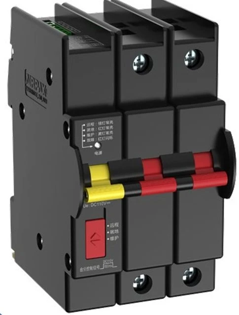
Airpax hydraulic-magnetic circuit breakers

Sensata
Remote-controlled circuit breakers
Airpax ICLR + ROCB Remote-Control Circuit Breaker

Contactors and relays

Hengstler
Signal relays (4/6 contacts)
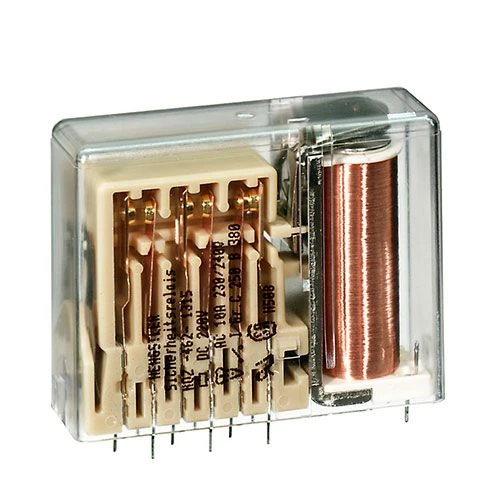
H-462 - Signal Relay (4 or 6 contacts)
Hengstler
Signal relays (8/10 contacts)
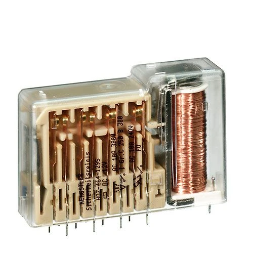
H-464 - Signal Relay (8 or 10 contacts)
Hengstler
Flat relays (4-10 contacts)
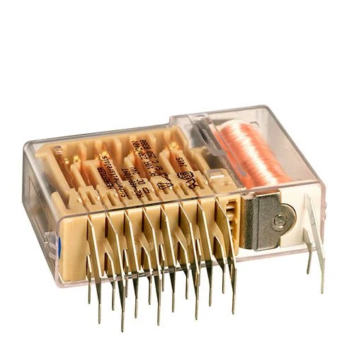
H-466 - Flat Relay (4–10 contacts)
Hengstler
Low-profile PCB relays (7 contacts)
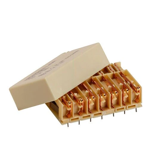
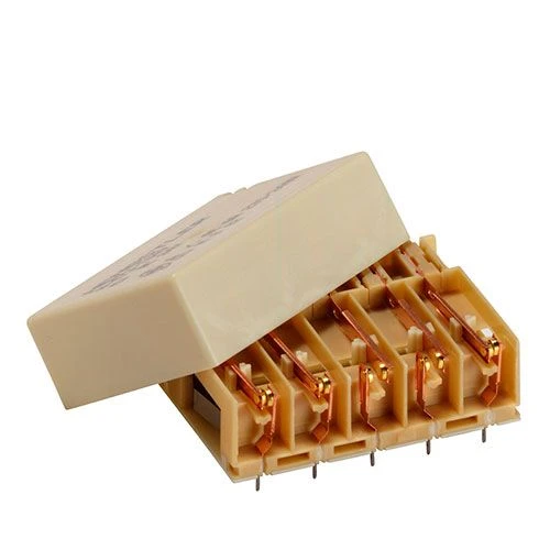
H-472 - Low-Profile PCB Relay (7 contacts)
Hengstler
Low-profile PCB relays (5 contacts)
H-473 - Low-Profile PCB Relay (5 contacts)

Enclosures and cabinets

nVent Schroff
Rugged IP67 enclosures
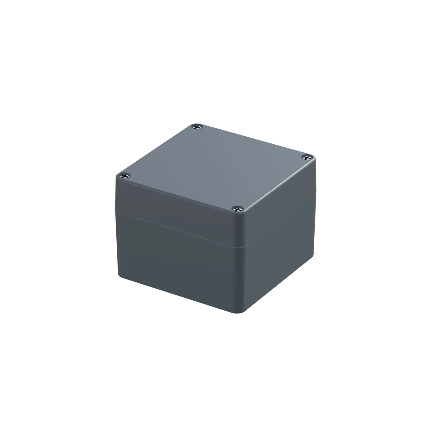
Rugged IP67 Small Form Factor Enclosure - IP-PRO Alu EMC
nVent Schroff
Outdoor wayside cabinets
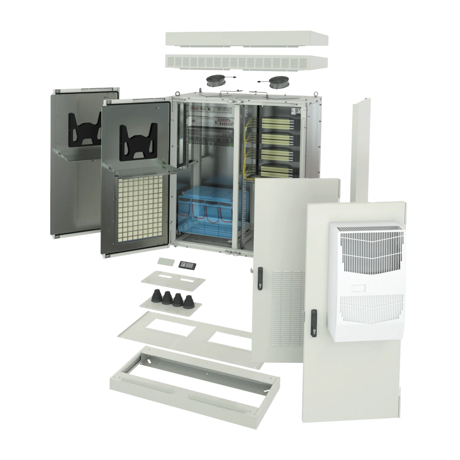
Wayside Outdoor Modular Cabinet

Equipment protection circuit breakers

Phoenix Contact
Equipment circuit breakers
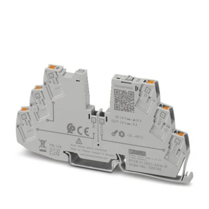
PTCB E1 - Electronic Circuit Breakers

Fibre optic boxes

Phoenix Contact
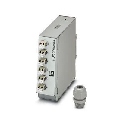
Fiber-optic distribution boxes
DIN-Rail Fiber Optic Boxes

Marking and labelling

Phoenix Contact
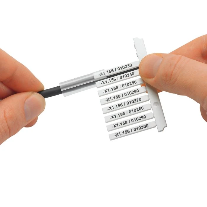
Cable markers for harsh environments
PATG HF and Metal Labels

Relays

Phoenix Contact
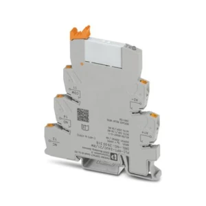
PLC-INTERFACE relay modules
PLC-INTERFACE - Electromechanical Relays
Phoenix Contact
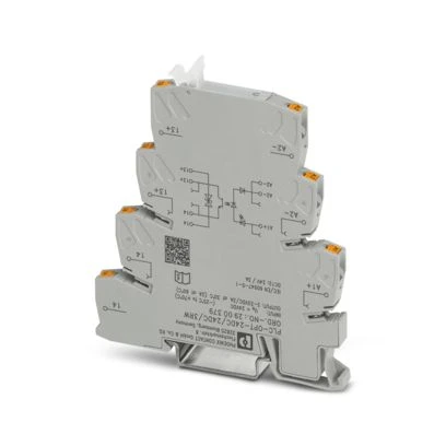
PLC-INTERFACE relay modules
PLC-INTERFACE - Solid-State Relays

Sensors, transducers and measurement

Hengstler
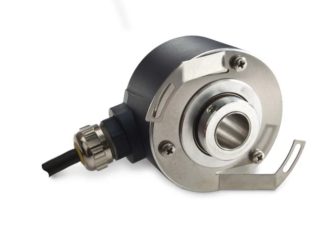
Absolute encoders for point-machine drives
AC58 / AD58 (SSI / Profinet)
Sensata
Encoders
Sensata/BEI PHO5 Multiturn Absolute Encoder (Ø14 mm Through Hollow Shaft, SSI)

Solid-state relays

Sensata
AC solid-state relays - panel mount
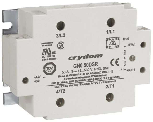
Crydom GN0 Panel-Mount AC Solid-State Relay (25/50 A)
Sensata
AC solid-state relays - DIN rail
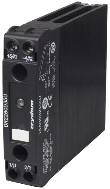
Crydom NOVA22 DR22 DIN-Rail AC Solid-State Relay (up to 35 A/600 V)
Sensata
AC solid-state relays - DIN rail
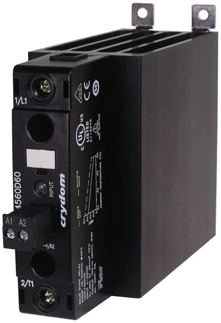
Crydom NOVA22 DR45 DIN-Rail AC Solid-State Relay (up to 60 A/600 V)
Sensata
AC solid-state relays - panel mount
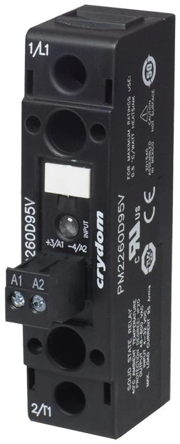
Crydom NOVA22 PM22 AC Solid-State Relay (up to 95 A/600 V)
Sensata
AC solid-state relays - panel mount
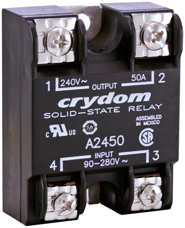
Crydom Series 1 Panel-Mount AC Solid-State Relay (10–125 A, 24–530 VAC)
Carlo Gavazzi
Solid-state relays
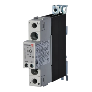
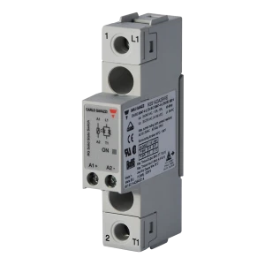
RGC (1-phase)
Carlo Gavazzi
Solid-state relays
RGC2 / RGC3
Carlo Gavazzi
Solid-state relays
RGH
Carlo Gavazzi
Solid-state relays
RGS

Surge protection

Phoenix Contact
Surge protection devices (SPD)
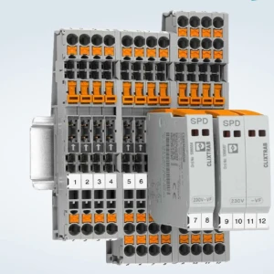
CLIXTRAB - Signal Circuit Protection

Selection criteria - Turnouts and switch drives

Selection criteria for this area:

  • Position monitoring as a safety function - the “switch blade closed” signal determines whether a permissive signal can be displayed; encoders and relays in this circuit should use redundancy and forcibly guided contacts; electronic solutions require an appropriate SIL level.
  • Track environment - vibration and shocks from passing trains, water, ice, salt and brake dust; a point-machine enclosure is not sealed like a cabinet, so equipment requires an appropriate degree of protection and temperature range.
  • Reversing drive - the motor changes direction each time the turnout is operated; reversing solid-state relays are selected for starting and stall current, with protection against energizing both directions simultaneously.
  • Heating - high-power resistance heaters are switched cyclically; current monitoring for each section detects a failed heater before the switch blade freezes.
  • Drive-current measurement - used for operation monitoring and detection of mechanical blockage from the current profile; the transducer is selected for starting current, not only operating current.
  • Surge protection - control and monitoring cables run along the track close to traction current; SPDs on control and signal circuits, plus galvanic isolation.
  • Resistance to sabotage and operating error - point locks, interlocks and locks; monitoring equipment installed inside the drive enclosure without external access.

Technical questions

How does the signal box know that a turnout has actually moved?

Control rods from the switch blades enter the drive enclosure, where measuring and monitoring devices verify the position of each blade; the confirmation signal is sent to the signal box, while an ammeter on the control panel shows the current drawn by the drives - the operator can see whether the drive is working. A gap greater than 30 mm must not be capable of being locked.

What is the difference between a trailable and a non-trailable point machine?

A trailable drive holds the switch blade against the stock rail with a force of up to 80 kN and yields if the turnout is run through from the trailing direction, protecting the mechanism; a non-trailable drive holds with a force of 250 kN and does not yield. The choice depends on track type and speed; high-speed turnouts use several drives on a single turnout.

Why are turnouts electrically heated?

To keep switch blades and locking mechanisms operational at low temperatures - snow and ice between the switch blade and stock rail prevent proper closure. Heating uses resistance wire installed along the stock rails and supplied from LPN points; gas heating was used in the past.

Why is the turnout circuit electrically insulated?

The switch-blade tie connects two rails that have different signal potentials in a track circuit; without insulation, the tie would short the track circuit and falsely indicate occupancy. Electrical insulation of the tie allows the track circuit to verify that the turnout is clear.