


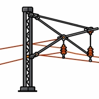
The overhead contact system comprises the contact line above the track and the return network in the rails - from the feeder point at the substation to the return-cable box. It is sectionalized: line disconnectors isolate a feeder from the contact line, section disconnectors divide the line into sections, and sectioning cabins with four high-speed circuit breakers split the section between substations so that a short circuit does not shut down an entire stretch, for example 30 km. More than 11,000 electrically operated disconnectors are in service on the PKP network and are remotely controlled from power control rooms; each has a pole-mounted box containing a motor, gearbox, control relays and position indication.
The return network is never fully insulated from earth - part of the traction current flows as stray current and causes corrosion of pipes, reinforcement and structures. Therefore, the resistance of a single rail must not exceed 0.2 Ω/km and that of the track 0.5 Ω/km; cross-bonds are installed approximately every 300 m (150 m near a substation), while supporting structures are bonded to the rails in groups through voltage-limiting devices that normally isolate the rails from earth and, in the event of an earth fault, convert it into a pole-to-pole short circuit that trips the protection. On lines with automatic block signalling, 1000 A impedance bonds pass traction current while blocking the signalling current of track circuits. Overvoltage protection of the contact line is provided by horn-type arresters (10 mm gap, 12 kV, every 1200–1300 m) and valve-type arresters; the follow current is interrupted by the circuit breakers in substations and sectioning cabins.
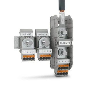
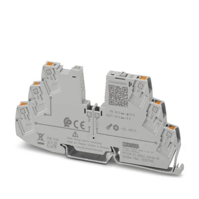
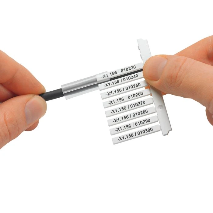
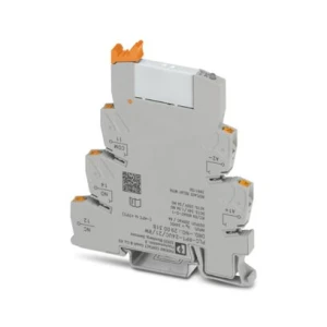
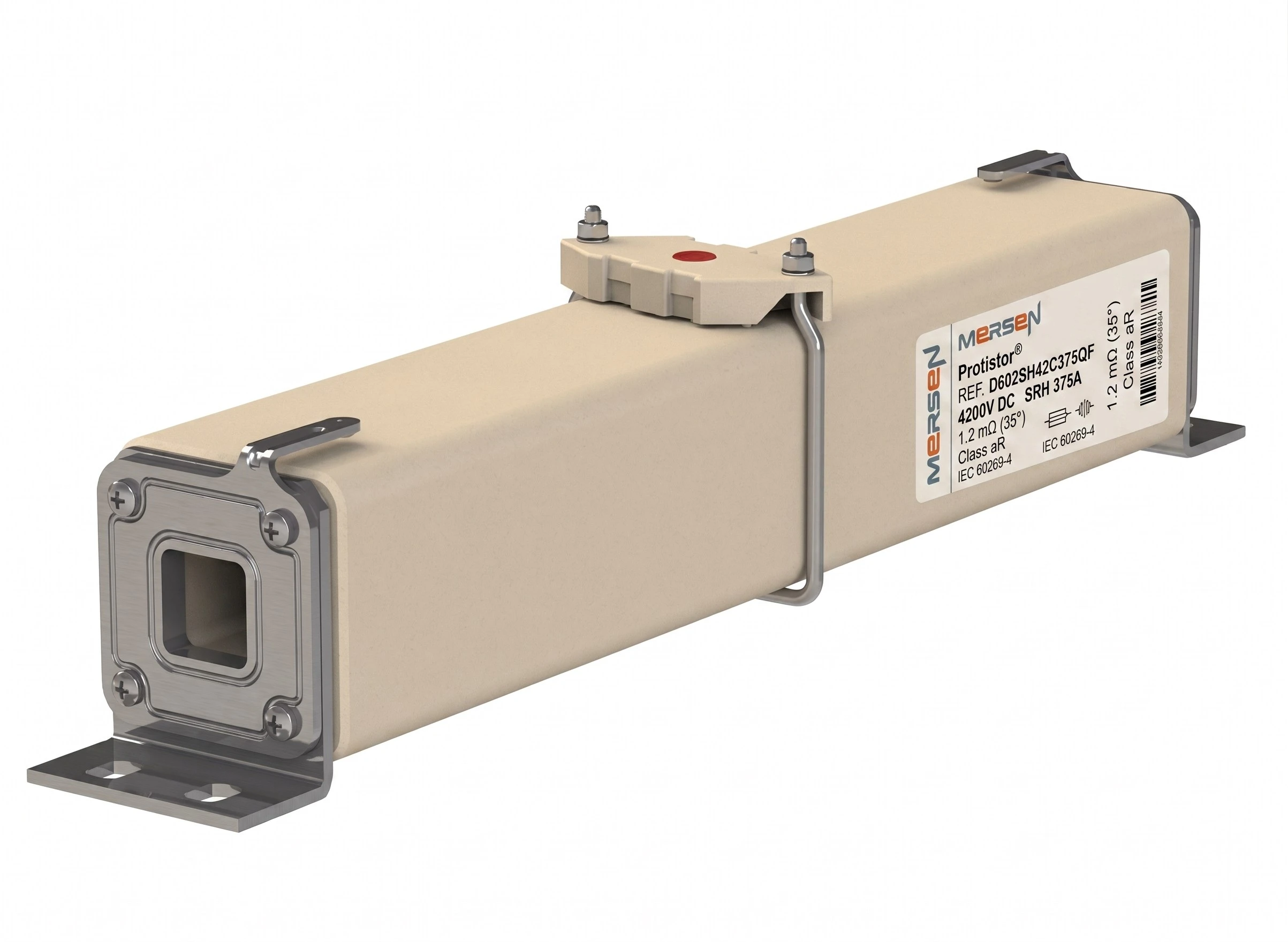
Equipment used in this area includes: apparatus for disconnector-drive boxes (relays, power supplies, motor-circuit protection, terminal blocks, surge protection devices and outdoor enclosures), control and indication circuits of sectioning cabins with backup batteries, overcurrent and undervoltage relays for cabin circuit breakers, voltage-limiting devices and rail-bonding spark gaps, fuses for measurement and auxiliary circuits, and high-current terminals for return cables.


Selection criteria for this area:
A line disconnector isolates the cable feeder from the overhead contact line, while a section disconnector divides the contact line into sections. Both provide only a visible isolation gap - they do not interrupt load current, so they are opened in a de-energized state after the high-speed circuit breaker has operated. A motor drive shortens switching time and allows disconnectors to be controlled remotely from a traction power control centre located tens of kilometres away.
Without it, a fault in the overhead line could de-energize the entire section between substations - even 30 km. The cabin is a container with a busbar and four high-speed circuit breakers interlocked with the substation breakers: during a fault, the cabin breaker and the cooperating substation breaker open, leaving only half of the section without voltage. Cross-connection between tracks is made with a bidirectional high-speed circuit breaker capable of interrupting current flowing in either direction.
Part of the return current leaves the rails and flows through the ground towards the substation, causing corrosion of pipes, reinforcement and structures; near the current collection point the rails have positive potential (anodic zone), while near the substation they have negative potential (cathodic zone). Stray currents are limited by keeping the return-network resistance low (rail ≤0.2 Ω/km, track ≤0.5 Ω/km), insulating joints and bonding connections, and balancing substation loading.
Under normal conditions it isolates the rails from the bonded structure, so stray currents do not flow through poles and foundations. During an earth fault on the structure, it conducts and converts the earth fault into an overhead-line-to-rail fault that trips the high-speed circuit breaker. Older spark gaps with mica plates broke down at approximately 100 V.