


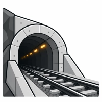
In tunnels and underground structures, we provide the layer between the power supply and the loads: enclosures and cabinets housing electrical apparatus, solid-state switching devices for ventilation, drainage pumps and heating circuits, energy and network-parameter metering in facility switchboards, and identification systems for cables and apparatus. Conditions are harsher than in a station building: humidity up to 100%, dust, vibration from passing trains, restricted service access and the electromagnetic field of the 3 kV DC traction system.
Volume V of the PKP PLK Technical Standards defines the framework for selecting these components. Equipment is kept outside the 5 m zone from the centreline of an electrified track; where this is impossible, metal structures and enclosures are bonded directly to the rails when resistance to reference earth is above 20 Ω and indirectly when it is below 20 Ω (PN-EN 50122-1), while conductors are routed in protective systems suitable for exposure to 3 kV DC. Protection against stray currents is governed by PN-EN 50122-2. Ventilation in enclosed and underground facilities is a load requiring enhanced continuity of supply - two independently supplied feeders are switched by an automatic transfer system. Circuits supplying distribution cabinets operate in a TT system with residual-current devices; sockets up to 20 A that are accessible to portable equipment use IΔn ≤ 30 mA protection. Varistors or protective diodes are used against supply-side overvoltages; permissible temporary overvoltages are Un + 250 V for disconnection times above 5 s and Un + 1200 V for times up to 5 s. Equipment status is reported to the local control centre using the states: ready, on, off and fault.
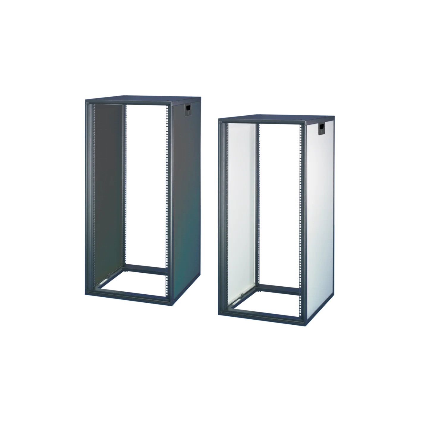
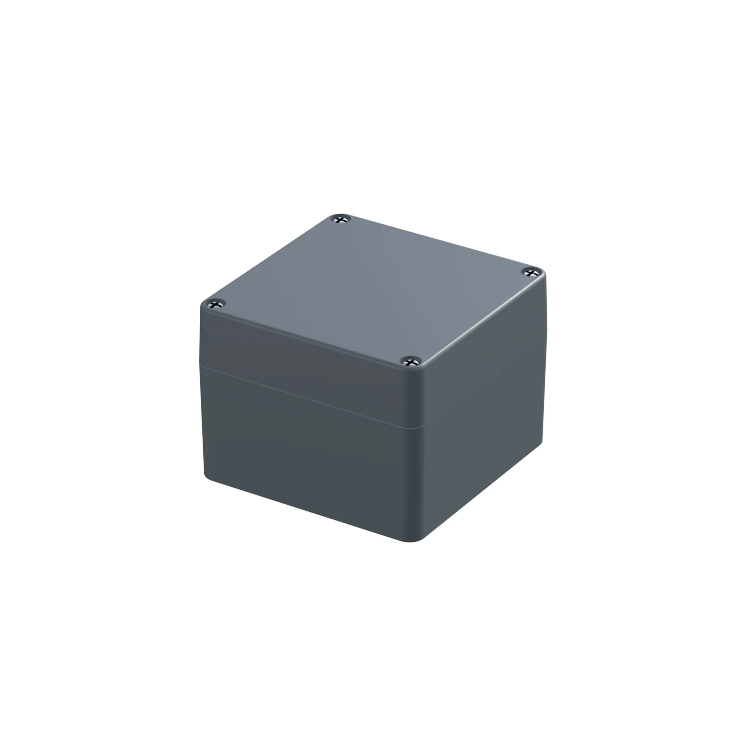
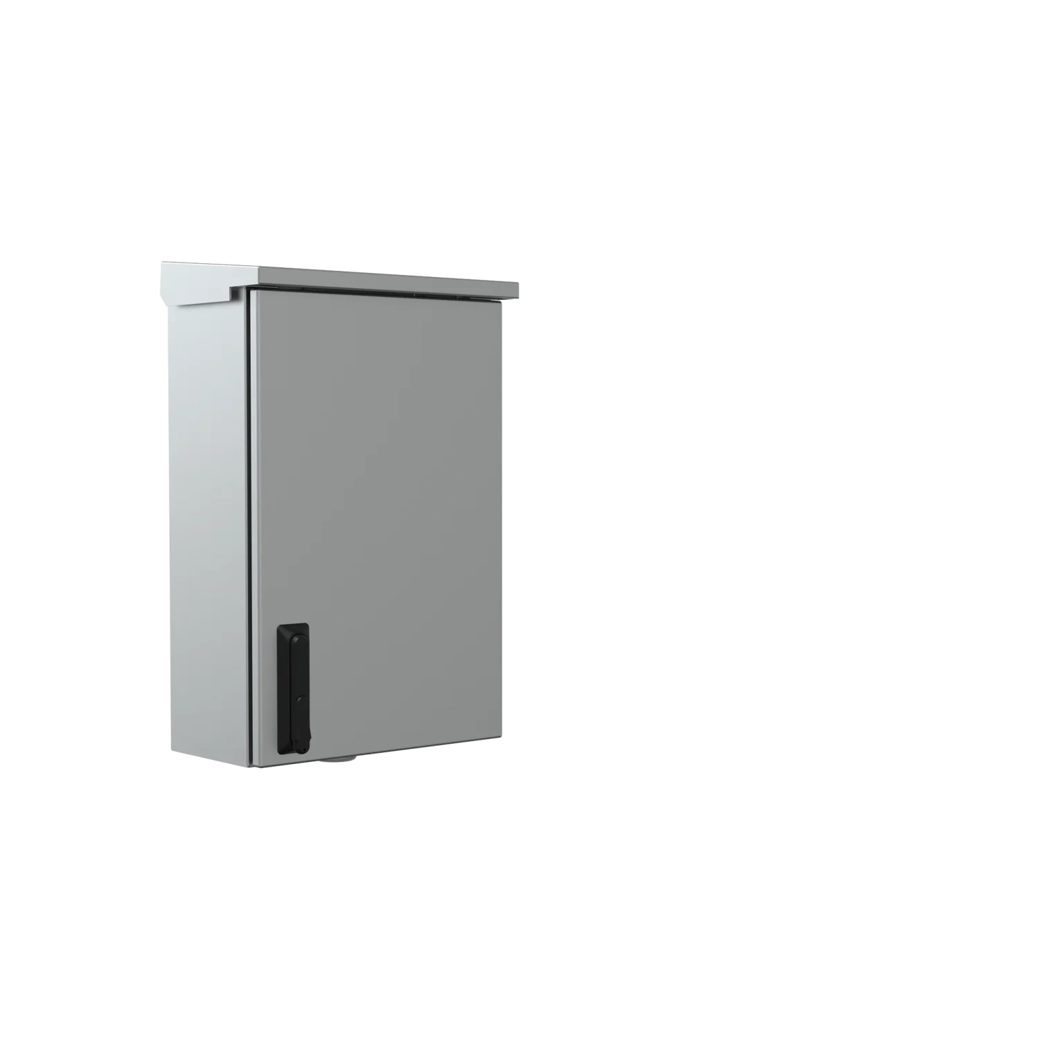
Products used here from our range include: the Varistar CP EMC & Signaling cabinet for trackside technical rooms (shielding up to 18 GHz, IP55, LSZH materials in accordance with EN 45545-2, resistance to trackside shock in accordance with EN 50125-3), AISI 304L/316L stainless-steel trackside enclosures rated IP66 and IK10, IP-PRO Alu EMC aluminium enclosures rated IP67 and IK09 with shielding from 30 MHz to 4 GHz and EN 61373 category 2 resistance, RGC2 and RGC3 solid-state relays for contactless switching of fans, pumps and heaters, WM20/WM30/WM40 network analysers for switchboard measurements, and PATG HF markers and metal plates for durable identification of cables and apparatus throughout the service life of the facility.


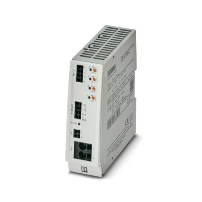
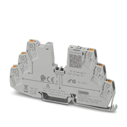
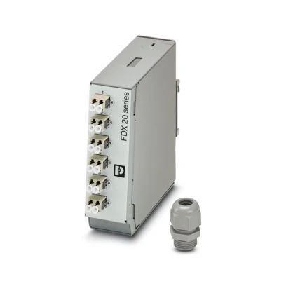
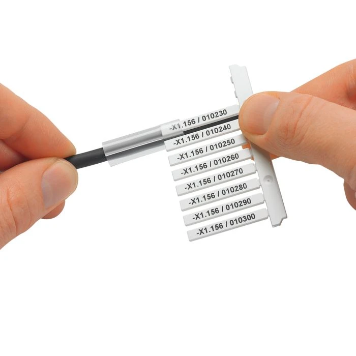

Selection criteria for this area:
A wall- or pole-mounted AISI 304L stainless-steel enclosure (optionally 316L), IP66 and IK10, tested to EN 50125-3, is suitable for power distribution, trackside radio communications and fibre-optic splices along the track - available in five sizes from 600×400×210 to 800×600×300 mm. A cast-aluminium IP-PRO Alu EMC enclosure up to IP67, IK09, EN 61373 category 2, −40…+90 °C, with structural shielding over 30 MHz–4 GHz, is suitable for small electronic assemblies in the most exposed locations. For a technical room near the tracks, a Varistar CP EMC & Signaling cabinet is appropriate: welded construction, IP55, shielding up to 18 GHz, and LSZH materials compliant with EN 45545-2.
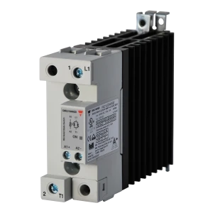
The deciding factors are switching frequency and service accessibility. A drainage pump and a sensor-controlled fan may switch many times per day - contactor contacts wear, while replacement in a tunnel can require track closure. RGC2 and RGC3 have no moving contacts, switch at zero crossing, support motors up to 20 kW at 42–660 VAC, provide 4000 Vrms insulation and SCCR 100 kA. The trade-off is semiconductor power loss: at higher currents forced-air cooling may be required, so cooling must be planned together with the cabinet layout.
By an EN 45545-2 declaration specifying the requirement set and hazard level. The Varistar CP EMC cabinet uses LSZH materials according to this standard, PATG HF markers meet R23 and R24 at HL1–HL3 and R22 at HL1–HL2, and RGC2/RGC3 relays list EN 45545-2 among their compliances. The manufacturer does not provide a fire declaration for metal labels - if the project requires one, it should be agreed before delivery.
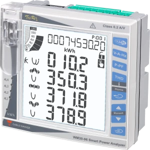
WM20/WM30/WM40 panel analysers in a 96 × 96 mm housing measure voltage, current, active/reactive/apparent power, power factor, frequency, energy, and voltage/current THD up to the 32nd harmonic, with class 0.5S active-energy accuracy. Modular expansion provides digital outputs, analogue I/O and Modbus RTU/TCP, BACnet IP/MS-TP or Profibus DPV0 communications. Volume V requires four statuses to be readable from the LCS: ready for operation, equipment on, equipment off, and fault.
Three things change. First, distance: equipment should be outside the 5 m zone from the centreline of an electrified track; at smaller distances direct bonding is used when the resistance of the metal structure to reference earth exceeds 20 Ω, and indirect bonding when it is lower (PN-EN 50122-1). Second, cable routing - all power and control cables must be placed in protective conduits against 3 kV DC potential. Third, stray currents: structural protection measures according to PN-EN 50122-2 are required, and stray-current limitation also applies to installations in civil structures.