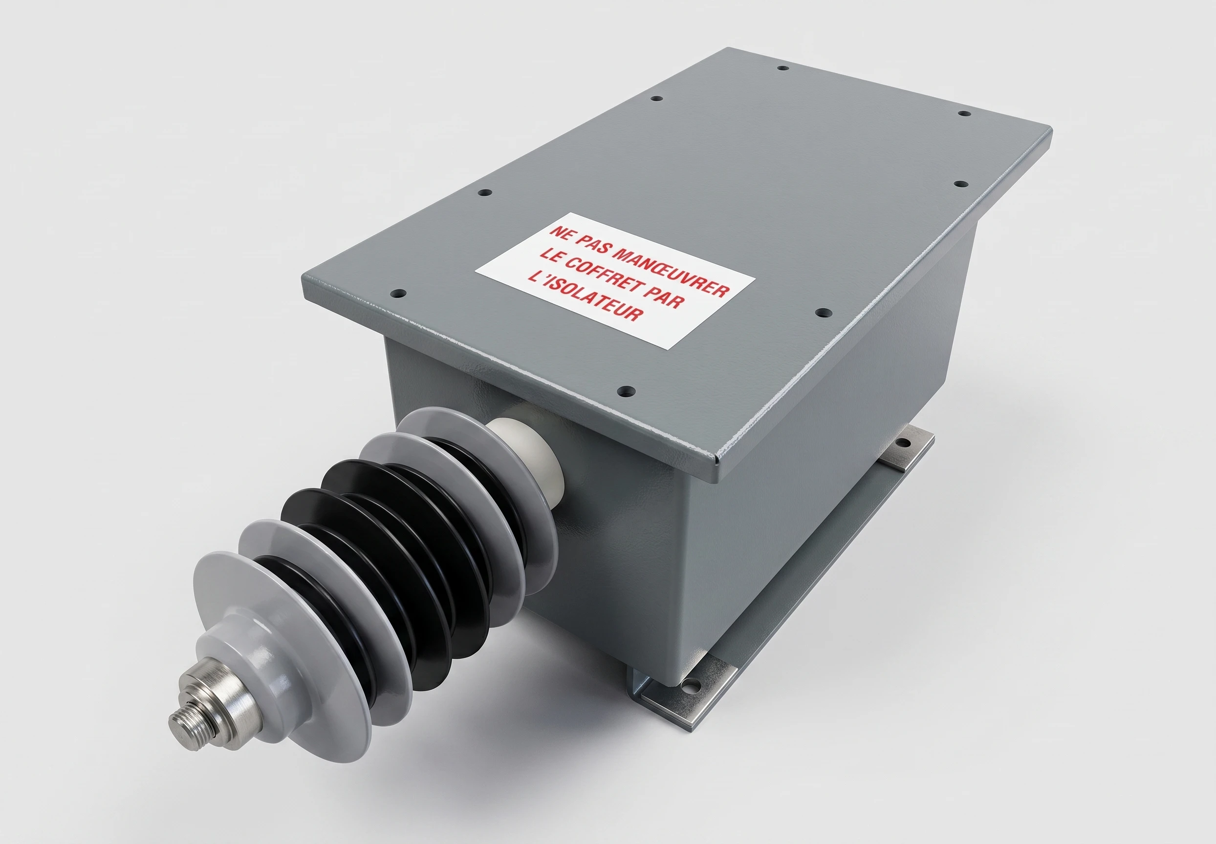
The surge arrester limits overvoltages between the supply conductor and earth in traction networks. A series fuse disconnects a failed varistor and keeps the line energized instead of transferring the trip to the substation high-speed circuit breaker. The zinc-oxide varistor operates without a series spark gap - the only series element is a current-limiting fuse. Maximum operating voltage 900 V DC, limiting voltage 1200 V DC; limiting characteristic from 1245 V at 0.1 kA through 1500 V at 5 kA and 1700 V at 10 kA to 2400 V at 100 kA peak. Response time 1 ns. The arrester operates bidirectionally with the same parameters for both polarities and carries no follow current - it clips voltage spikes only. Operating temperature −55…+85 °C, humidity up to 95% without condensation; Mersen permits salt atmosphere, dust particles of 0.1–1 mm, ozone, acid rain and SO₂ exposure.
Mersen specifies a rated voltage of 500–750 V AC at a limiting voltage of 1200 V DC and confirms that no tests were performed for 1.5 kV DC, 3 kV DC or 25 kV AC networks. Mersen provides two installation variants: a pole-mounted enclosure at feeder lines in substations along the route and a pantograph enclosure in vehicle roof circuits. The 10 kA version (drawing 118386) uses one AZE 030 T varistor module in a 435 × 255 × 204.5 mm enclosure; the 20 kA version (drawing 118515) uses two modules and has an overall length of 612 mm. M10 bolted connection, No. 8 AWG conductors at positive and negative terminals.
The series fuse in both versions is a Protistor size 122 aR 2000 V DC 400 A, ref. A079465 (CC 20 SRD 122 QF 0400): DC breaking capacity 100 kA, melting I²t 39,649 A²s, clearing I²t 219,000 A²s, according to IEC 60269-4. The spark-gap solution with a silicon-carbide resistor that this arrester replaces becomes conductive after several operations and causes the feeder breaker to open, interrupting traffic.
Fuse operation drives a striker that actuates a microswitch: a lamp on the enclosure cover indicates the affected line, while an alarm relay with a 110 V DC auxiliary contact transmits the state to remote supervision. The network operator can see that the arrester has been taken out of service without inspecting the route, and maintenance personnel know which component must be replaced before departure. In standby, the circuit draws only a few milliamps for indicator lamps and the relay coil.
Key features: